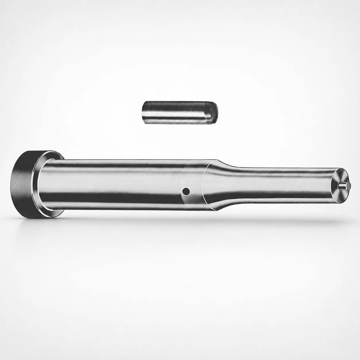
Metric Center Dowel Ejector Punches XCD Coating
Metric center dowel ejector punches with XCD coating are designed to support stable ejection while maintaining accurate locating in die sets. Their center dowel hole geometry helps transfer guide loads consistently for repeatable punch operation.
- Center dowel layout improves mold alignment and ejection repeatability.
- XCD coating enhances surface performance for wear resistance in production cycles.
- Tip and shank configurations support consistent insertion and controlled engagement.
- Commonly used in progressive and transfer tooling requiring precise ejector punch positioning.
Specifications
228 configurations available
| Tip shape | D (Shank dia.) (mm) | Jektole group | L1 (Point Length) (mm) | L (Length) (mm) | P Dimension (mm) | W Dimension (mm) | R Dimension (mm) |
|---|---|---|---|---|---|---|---|
| H | 10 | J6M | 19 ~ 25 | 71 ~ 130 | 4 ~ 4.49 | 4 ~ 4.49 | - |
| H | 10 | J6M | 19 ~ 25 | 71 ~ 130 | 4 ~ 4.49 | 4.5 ~ 9.95 | - |
| H | 10 | J6M | 19 ~ 25 | 71 ~ 130 | 4.5 ~ 9.95 | 4 ~ 4.49 | - |
| H | 10 | J6M | 19 ~ 25 | 71 ~ 130 | 4.5 ~ 9.95 | 4.5 ~ 9.95 | - |
| H | 13 | J6M | 19 ~ 25 | 71 ~ 130 | 4 ~ 5.99 | 4 ~ 5.99 | - |
| H | 13 | J6M | 19 ~ 25 | 71 ~ 130 | 4 ~ 5.99 | 6 ~ 12.95 | - |
| H | 13 | J6M | 19 ~ 25 | 71 ~ 130 | 6 ~ 12.95 | 4 ~ 5.99 | - |
| H | 13 | J6M | 19 ~ 25 | 71 ~ 130 | 6 ~ 12.95 | 6 ~ 12.95 | - |
| H | 16 | J9M | 19 ~ 25 | 71 ~ 130 | 6 ~ 7.19 | 6 ~ 7.19 | - |
| H | 16 | J9M | 19 ~ 25 | 71 ~ 130 | 6 ~ 7.19 | 7.2 ~ 15.95 | - |
| H | 16 | J9M | 19 ~ 25 | 71 ~ 130 | 7.2 ~ 15.95 | 6 ~ 7.19 | - |
| H | 16 | J9M | 19 ~ 25 | 71 ~ 130 | 7.2 ~ 15.95 | 7.2 ~ 15.95 | - |
| H | 20 | J9M | 19 ~ 25 | 71 ~ 130 | 6 ~ 7.99 | 6 ~ 7.99 | - |
| H | 20 | J9M | 19 ~ 25 | 71 ~ 130 | 6 ~ 7.99 | 8 ~ 19.95 | - |
| H | 20 | J9M | 19 ~ 25 | 71 ~ 130 | 8 ~ 19.95 | 6 ~ 7.99 | - |
| H | 20 | J9M | 19 ~ 25 | 71 ~ 130 | 8 ~ 19.95 | 8 ~ 19.95 | - |
| H | 25 | J9M | 19 ~ 25 | 71 ~ 130 | 6 ~ 8.99 | 6 ~ 8.99 | - |
| H | 25 | J9M | 19 ~ 25 | 71 ~ 130 | 6 ~ 8.99 | 9 ~ 24.95 | - |
| H | 25 | J9M | 19 ~ 25 | 71 ~ 130 | 9 ~ 24.95 | 6 ~ 8.99 | - |
| H | 25 | J9M | 19 ~ 25 | 71 ~ 130 | 9 ~ 24.95 | 9 ~ 24.95 | - |
| H | 32 | J9M | 25 ~ 30 | 71 ~ 130 | 7.2 ~ 9.99 | 7.2 ~ 9.99 | - |
| H | 32 | J9M | 25 ~ 30 | 71 ~ 130 | 7.2 ~ 9.99 | 10 ~ 31.95 | - |
| H | 32 | J9M | 25 ~ 30 | 71 ~ 130 | 10 ~ 31.95 | 7.2 ~ 9.99 | - |
| H | 32 | J9M | 25 ~ 30 | 71 ~ 130 | 10 ~ 31.95 | 10 ~ 31.95 | - |
| J | 10 | J6M | 19 ~ 25 | 71 ~ 130 | 4 ~ 4.49 | 4 ~ 4.49 | - |
| J | 10 | J6M | 19 ~ 25 | 71 ~ 130 | 4 ~ 4.49 | 4.5 ~ 9.95 | - |
| J | 10 | J6M | 19 ~ 25 | 71 ~ 130 | 4.5 ~ 9.95 | 4 ~ 4.49 | - |
| J | 10 | J6M | 19 ~ 25 | 71 ~ 130 | 4.5 ~ 9.95 | 4.5 ~ 9.95 | - |
| J | 13 | J6M | 19 ~ 25 | 71 ~ 130 | 4 ~ 5.99 | 4 ~ 5.99 | - |
| J | 13 | J6M | 19 ~ 25 | 71 ~ 130 | 4 ~ 5.99 | 6 ~ 12.95 | - |
| J | 13 | J6M | 19 ~ 25 | 71 ~ 130 | 6 ~ 12.95 | 4 ~ 5.99 | - |
| J | 13 | J6M | 19 ~ 25 | 71 ~ 130 | 6 ~ 12.95 | 6 ~ 12.95 | - |
| J | 16 | J9M | 19 ~ 25 | 71 ~ 130 | 6 ~ 7.19 | 6 ~ 7.19 | - |
| J | 16 | J9M | 19 ~ 25 | 71 ~ 130 | 6 ~ 7.19 | 7.2 ~ 15.95 | - |
| J | 16 | J9M | 19 ~ 25 | 71 ~ 130 | 7.2 ~ 15.95 | 6 ~ 7.19 | - |
| J | 16 | J9M | 19 ~ 25 | 71 ~ 130 | 7.2 ~ 15.95 | 7.2 ~ 15.95 | - |
| J | 20 | J9M | 19 ~ 25 | 71 ~ 130 | 6 ~ 7.99 | 6 ~ 7.99 | - |
| J | 20 | J9M | 19 ~ 25 | 71 ~ 130 | 6 ~ 7.99 | 8 ~ 19.95 | - |
| J | 20 | J9M | 19 ~ 25 | 71 ~ 130 | 8 ~ 19.95 | 6 ~ 7.99 | - |
| J | 20 | J9M | 19 ~ 25 | 71 ~ 130 | 8 ~ 19.95 | 8 ~ 19.95 | - |
| J | 25 | J9M | 19 ~ 25 | 71 ~ 130 | 6 ~ 8.99 | 6 ~ 8.99 | - |
| J | 25 | J9M | 19 ~ 25 | 71 ~ 130 | 6 ~ 8.99 | 9 ~ 24.95 | - |
| J | 25 | J9M | 19 ~ 25 | 71 ~ 130 | 9 ~ 24.95 | 6 ~ 8.99 | - |
| J | 25 | J9M | 19 ~ 25 | 71 ~ 130 | 9 ~ 24.95 | 9 ~ 24.95 | - |
| J | 32 | J9M | 25 ~ 30 | 71 ~ 130 | 7.2 ~ 9.99 | 7.2 ~ 9.99 | - |
| J | 32 | J9M | 25 ~ 30 | 71 ~ 130 | 7.2 ~ 9.99 | 10 ~ 31.95 | - |
| J | 32 | J9M | 25 ~ 30 | 71 ~ 130 | 10 ~ 31.95 | 7.2 ~ 9.99 | - |
| J | 32 | J9M | 25 ~ 30 | 71 ~ 130 | 10 ~ 31.95 | 10 ~ 31.95 | - |
| K | 10 | J6M | 19 ~ 25 | 71 ~ 130 | 4 ~ 4.49 | 4 ~ 4.49 | 0.2 ~ 4.975 |
| K | 10 | J6M | 19 ~ 25 | 71 ~ 130 | 4 ~ 4.49 | 4.5 ~ 9.95 | 0.2 ~ 4.975 |
Product Guide
Application Scenarios+
Metric center dowel ejector punches are used in injection mold tool sets where reliable ejection and tight alignment are critical. The integrated center dowel hole geometry helps transfer guide loads consistently, reducing misalignment during punch stroke and improving repeatability in progressive and transfer tooling.
- Automotive and appliance housings: ideal for ejection stages that must maintain position across high cycle counts; the XCD coating variant supports smoother, more stable punch sliding behavior.
- Precision connector and insert molds: suited when guide load transfer through the center dowel helps keep punch-to-die alignment consistent for uniform part release.
- Medical device component tooling: beneficial where repeatable ejector performance reduces the risk of partial ejection and downstream defects.
Choose the specific tip shape and shank diameter options to match the mold’s ejector layout while leveraging the XCD coating for improved surface performance under production wear conditions.
Material & Process Details+
The provided configuration specifies the XCD coating for the center dowel ejector punch surface, aimed at smoother operation and better wear behavior during repeated ejection. However, the input data does not list a specific steel grade, hardness (HRC), or a defined heat treatment state (e.g., quenched & tempered, nitrided), so those material properties cannot be stated from the current information.
- Coating effect: XCD is selected to enhance surface performance for wear resistance in production cycles, which typically reduces friction-related stick-slip during punch travel.
- Trade-off: coatings improve sliding/wear behavior, but dimensional stability and coating thickness limits must be considered when matching tight ejector clearances and tolerances.
If you need the exact base steel (e.g., H13-equivalent) and target hardness for cycle-life modeling, request the material/heat-treatment datasheet for series 250301826424.
Sizing & Selection Guide+
Select this center dowel ejector punch by matching the mold’s ejector requirements to the available metric dimensions in the specification.
- Shank diameter (D): choose from 10, 13, 16, 20, 25, 32 mm based on the guide pin/ejector bore sizing in the die set.
- Total length (L): select within the fixed range 71–130 mm to ensure full stroke coverage without bottoming in the stack.
- Point length (L1): match the required engagement depth using 19–25 mm or 25–30 mm, depending on part geometry and ejector contact area.
- Geometry controls: choose tip shape (H, J, K, L, N, O, R, V, X, Y, Z) and confirm the P and W features fall within P = 4–16 mm, W = 4–10 mm.
- Radial feature (R): select the appropriate R range based on the required clearance/contour: 0.2–4.975, 0.2–6.475, 0.2–7.975, 0.2–9.975, 0.2–12.475, or 0.2–15.975.
For fit, verify that your ejector bore and center-dowel locating interfaces accommodate the selected geometry while maintaining working clearance for smooth travel, especially with the XCD-coated surface.
Frequently Asked Questions
How do I choose the correct shank diameter (D) for the die set ejector bore?+
What total length (L) range should I use to cover the required ejector stroke?+
When should I select point length (L1) of 19–25 mm versus 25–30 mm?+
How do tip shape options (H, J, K, L, N, O, R, V, X, Y, Z) affect ejector contact and alignment?+
What do the P, W, and R dimension ranges imply for mold clearance and fitting?+
Related Products

Metric Center Dowel Ejector Punches (SKD11 Equivalent)

Dicoat Treatment SKD11 Steel Center Dowel Ejector Punches - Metric

Center Dowel Ejector Punches - Metric, XCN TiCN Coating

DIN Standard SKD11 Steel Gas Release Single-Stepped Ejector Punches

Center Dowel Ejector Punches with Locating Dowel Hole

DIN Standard TiCN Center Dowel Ejector Punches
Need Custom Specifications?
Our engineering team can help with custom configurations, material selection, and volume pricing.