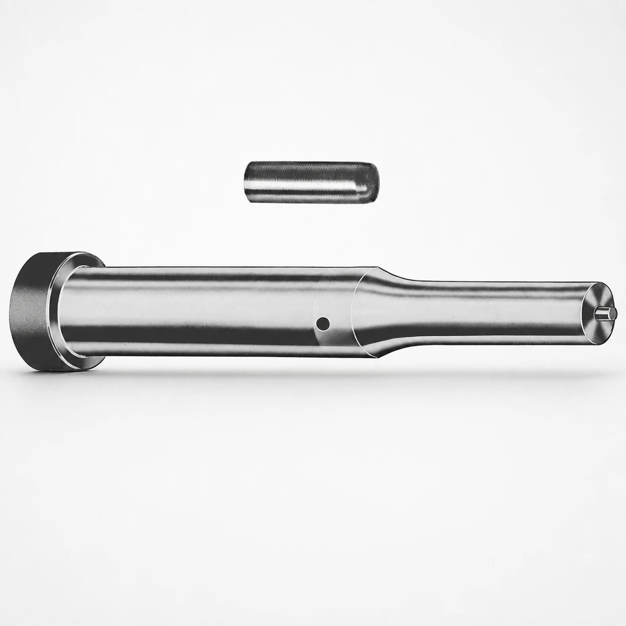
Metric Steel Center Dowel Ejector Punches XNT DayTiN® Coating
Center Dowel Ejector Punches (Metric) (DayTiN® coated) are designed to deliver accurate centering and reliable ejection in precision die work. The XNT DayTiN® surface helps reduce wear and supports consistent punch performance over repeat cycles.
- Center-dowel ejector punch geometry improves alignment during ejection
- XNT DayTiN® coating provides enhanced surface durability for tool life
- Metric build supports standard die layouts and efficient procurement
- Appropriate for automotive, electronics, and general forming die applications
Specifications
228 configurations available
| Tip shape | D (Shank dia.) (mm) | Jektole group | L1 (Point Length) (mm) | L (Length) (mm) | P Dimension (mm) | W Dimension (mm) | R Dimension (mm) |
|---|---|---|---|---|---|---|---|
| H | 10 | J6M | 19 ~ 25 | 71 ~ 130 | 4 ~ 4.49 | 4 ~ 4.49 | - |
| H | 10 | J6M | 19 ~ 25 | 71 ~ 130 | 4 ~ 4.49 | 4.5 ~ 9.95 | - |
| H | 10 | J6M | 19 ~ 25 | 71 ~ 130 | 4.5 ~ 9.95 | 4 ~ 4.49 | - |
| H | 10 | J6M | 19 ~ 25 | 71 ~ 130 | 4.5 ~ 9.95 | 4.5 ~ 9.95 | - |
| H | 13 | J6M | 19 ~ 25 | 71 ~ 130 | 4 ~ 5.99 | 4 ~ 5.99 | - |
| H | 13 | J6M | 19 ~ 25 | 71 ~ 130 | 4 ~ 5.99 | 6 ~ 12.95 | - |
| H | 13 | J6M | 19 ~ 25 | 71 ~ 130 | 6 ~ 12.95 | 4 ~ 5.99 | - |
| H | 13 | J6M | 19 ~ 25 | 71 ~ 130 | 6 ~ 12.95 | 6 ~ 12.95 | - |
| H | 16 | J9M | 19 ~ 25 | 71 ~ 130 | 6 ~ 7.19 | 6 ~ 7.19 | - |
| H | 16 | J9M | 19 ~ 25 | 71 ~ 130 | 6 ~ 7.19 | 7.2 ~ 15.95 | - |
| H | 16 | J9M | 19 ~ 25 | 71 ~ 130 | 7.2 ~ 15.95 | 6 ~ 7.19 | - |
| H | 16 | J9M | 19 ~ 25 | 71 ~ 130 | 7.2 ~ 15.95 | 7.2 ~ 15.95 | - |
| H | 20 | J9M | 19 ~ 25 | 71 ~ 130 | 6 ~ 7.99 | 6 ~ 7.99 | - |
| H | 20 | J9M | 19 ~ 25 | 71 ~ 130 | 6 ~ 7.99 | 8 ~ 19.95 | - |
| H | 20 | J9M | 19 ~ 25 | 71 ~ 130 | 8 ~ 19.95 | 6 ~ 7.99 | - |
| H | 20 | J9M | 19 ~ 25 | 71 ~ 130 | 8 ~ 19.95 | 8 ~ 19.95 | - |
| H | 25 | J9M | 19 ~ 25 | 71 ~ 130 | 6 ~ 8.99 | 6 ~ 8.99 | - |
| H | 25 | J9M | 19 ~ 25 | 71 ~ 130 | 6 ~ 8.99 | 9 ~ 24.95 | - |
| H | 25 | J9M | 19 ~ 25 | 71 ~ 130 | 9 ~ 24.95 | 6 ~ 8.99 | - |
| H | 25 | J9M | 19 ~ 25 | 71 ~ 130 | 9 ~ 24.95 | 9 ~ 24.95 | - |
| H | 32 | J9M | 25 ~ 30 | 71 ~ 130 | 7.2 ~ 9.99 | 7.2 ~ 9.99 | - |
| H | 32 | J9M | 25 ~ 30 | 71 ~ 130 | 7.2 ~ 9.99 | 10 ~ 31.95 | - |
| H | 32 | J9M | 25 ~ 30 | 71 ~ 130 | 10 ~ 31.95 | 7.2 ~ 9.99 | - |
| H | 32 | J9M | 25 ~ 30 | 71 ~ 130 | 10 ~ 31.95 | 10 ~ 31.95 | - |
| J | 10 | J6M | 19 ~ 25 | 71 ~ 130 | 4 ~ 4.49 | 4 ~ 4.49 | - |
| J | 10 | J6M | 19 ~ 25 | 71 ~ 130 | 4 ~ 4.49 | 4.5 ~ 9.95 | - |
| J | 10 | J6M | 19 ~ 25 | 71 ~ 130 | 4.5 ~ 9.95 | 4 ~ 4.49 | - |
| J | 10 | J6M | 19 ~ 25 | 71 ~ 130 | 4.5 ~ 9.95 | 4.5 ~ 9.95 | - |
| J | 13 | J6M | 19 ~ 25 | 71 ~ 130 | 4 ~ 5.99 | 4 ~ 5.99 | - |
| J | 13 | J6M | 19 ~ 25 | 71 ~ 130 | 4 ~ 5.99 | 6 ~ 12.95 | - |
| J | 13 | J6M | 19 ~ 25 | 71 ~ 130 | 6 ~ 12.95 | 4 ~ 5.99 | - |
| J | 13 | J6M | 19 ~ 25 | 71 ~ 130 | 6 ~ 12.95 | 6 ~ 12.95 | - |
| J | 16 | J9M | 19 ~ 25 | 71 ~ 130 | 6 ~ 7.19 | 6 ~ 7.19 | - |
| J | 16 | J9M | 19 ~ 25 | 71 ~ 130 | 6 ~ 7.19 | 7.2 ~ 15.95 | - |
| J | 16 | J9M | 19 ~ 25 | 71 ~ 130 | 7.2 ~ 15.95 | 6 ~ 7.19 | - |
| J | 16 | J9M | 19 ~ 25 | 71 ~ 130 | 7.2 ~ 15.95 | 7.2 ~ 15.95 | - |
| J | 20 | J9M | 19 ~ 25 | 71 ~ 130 | 6 ~ 7.99 | 6 ~ 7.99 | - |
| J | 20 | J9M | 19 ~ 25 | 71 ~ 130 | 6 ~ 7.99 | 8 ~ 19.95 | - |
| J | 20 | J9M | 19 ~ 25 | 71 ~ 130 | 8 ~ 19.95 | 6 ~ 7.99 | - |
| J | 20 | J9M | 19 ~ 25 | 71 ~ 130 | 8 ~ 19.95 | 8 ~ 19.95 | - |
| J | 25 | J9M | 19 ~ 25 | 71 ~ 130 | 6 ~ 8.99 | 6 ~ 8.99 | - |
| J | 25 | J9M | 19 ~ 25 | 71 ~ 130 | 6 ~ 8.99 | 9 ~ 24.95 | - |
| J | 25 | J9M | 19 ~ 25 | 71 ~ 130 | 9 ~ 24.95 | 6 ~ 8.99 | - |
| J | 25 | J9M | 19 ~ 25 | 71 ~ 130 | 9 ~ 24.95 | 9 ~ 24.95 | - |
| J | 32 | J9M | 25 ~ 30 | 71 ~ 130 | 7.2 ~ 9.99 | 7.2 ~ 9.99 | - |
| J | 32 | J9M | 25 ~ 30 | 71 ~ 130 | 7.2 ~ 9.99 | 10 ~ 31.95 | - |
| J | 32 | J9M | 25 ~ 30 | 71 ~ 130 | 10 ~ 31.95 | 7.2 ~ 9.99 | - |
| J | 32 | J9M | 25 ~ 30 | 71 ~ 130 | 10 ~ 31.95 | 10 ~ 31.95 | - |
| K | 10 | J6M | 19 ~ 25 | 71 ~ 130 | 4 ~ 4.49 | 4 ~ 4.49 | 0.2 ~ 4.975 |
| K | 10 | J6M | 19 ~ 25 | 71 ~ 130 | 4 ~ 4.49 | 4.5 ~ 9.95 | 0.2 ~ 4.975 |
Product Guide
Application Scenarios+
These center-dowel ejector punches are used in injection molding and precision die tooling where repeatable centering and smooth stroke-to-stroke ejection are critical. The keyed shank and center-dowel geometry help maintain alignment through the ejection phase, reducing side loading on the guide components.
- Automotive connector and bracket molds: In high-cycle tooling, the XNT DayTiN® coated surface supports consistent ejection with improved resistance to scuffing and abrasive wear from repeated contact during cycling.
- Electronics housings and enclosures: The stable centering reduces misalignment-related flash risk in thin-wall parts by keeping the ejector action coaxial during opening.
- General forming and progressive die sets: Available tip shapes (H, J, K, L, N, O, R, V, X, Y, Z) and metric sizing make it easier to match existing die layouts while supporting reliable punching/ejection in dependable forming operations.
Material & Process Details+
The product data provided specifies the XNT DayTiN® coating focus for stable ejection and tool durability, but it does not list the underlying steel grade or a corresponding heat-treatment state (e.g., quenched & tempered, nitrided). For selection at the tooling level, treat the coating as the primary functional specification available here.
- XNT DayTiN® coating: Designed to enhance surface wear resistance and help maintain low friction during repeated punch/dowel contact.
- Wear vs. toughness trade-off: Coatings generally improve abrasion/scuff resistance at the surface while relying on the base steel’s toughness for impact and bending performance; since base hardness and grade are not provided, verify with the supplier’s technical datasheet for critical load cases.
- Heat treatment & hardness: Not specified in the provided information—confirm hardness (HRC) and heat treatment state for tool-life calculations.
Sizing & Selection Guide+
Select the ejector punch dimensions by matching the shank diameter and working length to the guide system, then tune the point geometry to the cavity/core clearance and ejection requirement.
- Shank diameter (D, mm): choose from 10, 13, 16, 20, 25, 32 to fit the die guide and dowel hole sizing.
- Overall length (L, mm): fixed range 71 ~ 130—select based on shut height, stroke envelope, and clearance to the back plate.
- Point length (L1, mm): options 19 ~ 25 or 25 ~ 30 to control penetration depth and contact area at ejection.
- Other geometry controls: match P (4 ~ 16 mm), W (4 ~ 10 mm), and R (0.2 ~ 4.975 up to 0.2 ~ 15.975 mm depending on configuration) to the required profile and clearance to reduce edge stress.
Confirm tolerances and fit using your die designer’s standard (e.g., guide hole and dowel clearance). The only fixed dimension stated is the overall length range (L), while D, tip shape, L1, P, W, and R are variable by configuration.
Frequently Asked Questions
Which tip shapes (H, J, K, L, N, O, R, V, X, Y, Z) are typically used to optimize ejection alignment in center-dowel applications?+
The tip shape is a configurable parameter for this series, allowing you to tailor the point geometry to the part contact requirements and the ejector travel path. For center-dowel ejector punches with dowel holes, choosing a tip profile that matches your clearance and contact area helps maintain consistent coaxial action during ejection. Use the appropriate L1 (19 ~ 25 mm or 25 ~ 30 mm) together with the correct D (10, 13, 16, 20, 25, 32 mm) to ensure alignment and controlled penetration.
How do I select the correct shank diameter D for fitting in metric tooling guide systems?+
This series provides metric shank diameters D = 10, 13, 16, 20, 25, 32 mm. Match D to the diameter of your ejector guide bore and dowel-related components so the punch can travel without excessive lateral load. If you are upgrading an existing tool, verify your current bore diameter and clearance standard, then select the closest D and confirm tolerances for smooth cycling.
What is the relationship between L and L1 when designing ejector clearance and point engagement?+
L is the overall length and is specified as 71 ~ 130 mm, which you should base on the full stroke envelope and distances to plates/backing surfaces. L1 is the point length (19 ~ 25 mm or 25 ~ 30 mm) and controls how far the tip reaches into/against the part region during ejection. Selecting L for clearance and selecting L1 for engagement helps prevent interference and reduces uneven contact.
Does the XNT DayTiN® coating affect wear resistance and why is it beneficial for high-cycle punching/ejection?+
The provided description highlights that the XNT DayTiN® coating improves surface durability and supports consistent punch performance over repeat cycles. In high-cycle automotive and electronics tooling, this can reduce wear-related performance drift and help maintain smooth ejection by resisting scuffing/abrasive surface degradation. For exact wear and friction outcomes, validate against your part material and cycle rate, since base steel hardness and heat treatment are not specified in the provided data.
How do I choose P, W, and R dimensions for profile clearance and stress reduction around the dowel hole area?+
This series allows configuring P (4 ~ 16 mm), W (4 ~ 10 mm), and R with ranges from 0.2 ~ 4.975 up to 0.2 ~ 15.975 mm depending on configuration. These parameters define the detailed profile and radii, which directly influence local contact, edge loading, and clearance to surrounding die elements. Select combinations that satisfy your cavity/core clearance and minimize sharp transitions, then confirm the final stack-up with your guide and dowel hole tolerances.
Related Products

Metric Center Dowel Ejector Punches (SKD11 Equivalent)

Dicoat Treatment SKD11 Steel Center Dowel Ejector Punches - Metric

Center Dowel Ejector Punches - Metric, XCN TiCN Coating

DIN Standard SKD11 Steel Gas Release Single-Stepped Ejector Punches

Center Dowel Ejector Punches with Locating Dowel Hole

DIN Standard TiCN Center Dowel Ejector Punches
Need Custom Specifications?
Our engineering team can help with custom configurations, material selection, and volume pricing.