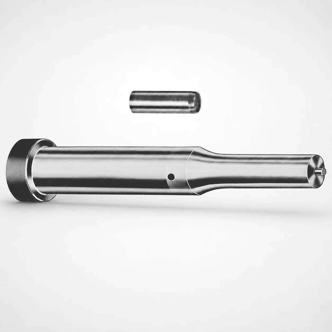
Center Dowel Ejector Punches - Metric CRN Coating
Center Dowel Ejector Punches - Metric (CRN Coating) provide controlled ejection and reliable centering in die and mold operations. The coated punch surface supports consistent performance under production wear.
- Center dowel design improves alignment for repeatable ejection cycles
- CRN Coating helps resist abrasion and extends punch service life
- Metric geometry supports stable fit around locating features
- Commonly used in precision tooling for progressive dies and molds
Specifications
228 configurations available
| Tip shape | D (Shank dia.) (mm) | Jektole group | L1 (Point Length) (mm) | L (Length) (mm) | P Dimension (mm) | W Dimension (mm) | R Dimension (mm) |
|---|---|---|---|---|---|---|---|
| H | 10 | J6M | 19 ~ 25 | 71 ~ 130 | 4 ~ 4.49 | 4 ~ 4.49 | - |
| H | 10 | J6M | 19 ~ 25 | 71 ~ 130 | 4 ~ 4.49 | 4.5 ~ 9.95 | - |
| H | 10 | J6M | 19 ~ 25 | 71 ~ 130 | 4.5 ~ 9.95 | 4 ~ 4.49 | - |
| H | 10 | J6M | 19 ~ 25 | 71 ~ 130 | 4.5 ~ 9.95 | 4.5 ~ 9.95 | - |
| H | 13 | J6M | 19 ~ 25 | 71 ~ 130 | 4 ~ 5.99 | 4 ~ 5.99 | - |
| H | 13 | J6M | 19 ~ 25 | 71 ~ 130 | 4 ~ 5.99 | 6 ~ 12.95 | - |
| H | 13 | J6M | 19 ~ 25 | 71 ~ 130 | 6 ~ 12.95 | 4 ~ 5.99 | - |
| H | 13 | J6M | 19 ~ 25 | 71 ~ 130 | 6 ~ 12.95 | 6 ~ 12.95 | - |
| H | 16 | J9M | 19 ~ 25 | 71 ~ 130 | 6 ~ 7.19 | 6 ~ 7.19 | - |
| H | 16 | J9M | 19 ~ 25 | 71 ~ 130 | 6 ~ 7.19 | 7.2 ~ 15.95 | - |
| H | 16 | J9M | 19 ~ 25 | 71 ~ 130 | 7.2 ~ 15.95 | 6 ~ 7.19 | - |
| H | 16 | J9M | 19 ~ 25 | 71 ~ 130 | 7.2 ~ 15.95 | 7.2 ~ 15.95 | - |
| H | 20 | J9M | 19 ~ 25 | 71 ~ 130 | 6 ~ 7.99 | 6 ~ 7.99 | - |
| H | 20 | J9M | 19 ~ 25 | 71 ~ 130 | 6 ~ 7.99 | 8 ~ 19.95 | - |
| H | 20 | J9M | 19 ~ 25 | 71 ~ 130 | 8 ~ 19.95 | 6 ~ 7.99 | - |
| H | 20 | J9M | 19 ~ 25 | 71 ~ 130 | 8 ~ 19.95 | 8 ~ 19.95 | - |
| H | 25 | J9M | 19 ~ 25 | 71 ~ 130 | 6 ~ 8.99 | 6 ~ 8.99 | - |
| H | 25 | J9M | 19 ~ 25 | 71 ~ 130 | 6 ~ 8.99 | 9 ~ 24.95 | - |
| H | 25 | J9M | 19 ~ 25 | 71 ~ 130 | 9 ~ 24.95 | 6 ~ 8.99 | - |
| H | 25 | J9M | 19 ~ 25 | 71 ~ 130 | 9 ~ 24.95 | 9 ~ 24.95 | - |
| H | 32 | J9M | 25 ~ 30 | 71 ~ 130 | 7.2 ~ 9.99 | 7.2 ~ 9.99 | - |
| H | 32 | J9M | 25 ~ 30 | 71 ~ 130 | 7.2 ~ 9.99 | 10 ~ 31.95 | - |
| H | 32 | J9M | 25 ~ 30 | 71 ~ 130 | 10 ~ 31.95 | 7.2 ~ 9.99 | - |
| H | 32 | J9M | 25 ~ 30 | 71 ~ 130 | 10 ~ 31.95 | 10 ~ 31.95 | - |
| J | 10 | J6M | 19 ~ 25 | 71 ~ 130 | 4 ~ 4.49 | 4 ~ 4.49 | - |
| J | 10 | J6M | 19 ~ 25 | 71 ~ 130 | 4 ~ 4.49 | 4.5 ~ 9.95 | - |
| J | 10 | J6M | 19 ~ 25 | 71 ~ 130 | 4.5 ~ 9.95 | 4 ~ 4.49 | - |
| J | 10 | J6M | 19 ~ 25 | 71 ~ 130 | 4.5 ~ 9.95 | 4.5 ~ 9.95 | - |
| J | 13 | J6M | 19 ~ 25 | 71 ~ 130 | 4 ~ 5.99 | 4 ~ 5.99 | - |
| J | 13 | J6M | 19 ~ 25 | 71 ~ 130 | 4 ~ 5.99 | 6 ~ 12.95 | - |
| J | 13 | J6M | 19 ~ 25 | 71 ~ 130 | 6 ~ 12.95 | 4 ~ 5.99 | - |
| J | 13 | J6M | 19 ~ 25 | 71 ~ 130 | 6 ~ 12.95 | 6 ~ 12.95 | - |
| J | 16 | J9M | 19 ~ 25 | 71 ~ 130 | 6 ~ 7.19 | 6 ~ 7.19 | - |
| J | 16 | J9M | 19 ~ 25 | 71 ~ 130 | 6 ~ 7.19 | 7.2 ~ 15.95 | - |
| J | 16 | J9M | 19 ~ 25 | 71 ~ 130 | 7.2 ~ 15.95 | 6 ~ 7.19 | - |
| J | 16 | J9M | 19 ~ 25 | 71 ~ 130 | 7.2 ~ 15.95 | 7.2 ~ 15.95 | - |
| J | 20 | J9M | 19 ~ 25 | 71 ~ 130 | 6 ~ 7.99 | 6 ~ 7.99 | - |
| J | 20 | J9M | 19 ~ 25 | 71 ~ 130 | 6 ~ 7.99 | 8 ~ 19.95 | - |
| J | 20 | J9M | 19 ~ 25 | 71 ~ 130 | 8 ~ 19.95 | 6 ~ 7.99 | - |
| J | 20 | J9M | 19 ~ 25 | 71 ~ 130 | 8 ~ 19.95 | 8 ~ 19.95 | - |
| J | 25 | J9M | 19 ~ 25 | 71 ~ 130 | 6 ~ 8.99 | 6 ~ 8.99 | - |
| J | 25 | J9M | 19 ~ 25 | 71 ~ 130 | 6 ~ 8.99 | 9 ~ 24.95 | - |
| J | 25 | J9M | 19 ~ 25 | 71 ~ 130 | 9 ~ 24.95 | 6 ~ 8.99 | - |
| J | 25 | J9M | 19 ~ 25 | 71 ~ 130 | 9 ~ 24.95 | 9 ~ 24.95 | - |
| J | 32 | J9M | 25 ~ 30 | 71 ~ 130 | 7.2 ~ 9.99 | 7.2 ~ 9.99 | - |
| J | 32 | J9M | 25 ~ 30 | 71 ~ 130 | 7.2 ~ 9.99 | 10 ~ 31.95 | - |
| J | 32 | J9M | 25 ~ 30 | 71 ~ 130 | 10 ~ 31.95 | 7.2 ~ 9.99 | - |
| J | 32 | J9M | 25 ~ 30 | 71 ~ 130 | 10 ~ 31.95 | 10 ~ 31.95 | - |
| K | 10 | J6M | 19 ~ 25 | 71 ~ 130 | 4 ~ 4.49 | 4 ~ 4.49 | 0.2 ~ 4.975 |
| K | 10 | J6M | 19 ~ 25 | 71 ~ 130 | 4 ~ 4.49 | 4.5 ~ 9.95 | 0.2 ~ 4.975 |
Product Guide
Application Scenarios+
Center dowel ejector punches are used in injection and die-casting tool sets where consistent part ejection must be synchronized with precise locating features. This metric punch variant is well-suited for tooling that cycles frequently, because the center dowel promotes repeatable alignment during travel and reduces the risk of side-loading.
In automotive and appliance insert die builds, these punches help maintain stable ejection of thin or complex parts by guiding the ejection motion through a defined center path. The CRN-coated working surface improves abrasion resistance, supporting stable performance as wear occurs at the sliding interface.
They are also effective in progressive die and multi-cavity mold assemblies where locating holes and ejector timing must stay consistent over long production runs. The available tip shapes and metric shank diameters allow matching the punch geometry to locating bushing and ejector clearance requirements.
- Use in die casting tool builds requiring durable wear resistance
- Best fit when central alignment is critical for stable ejection cycles
- CRN coating targets abrasion-driven wear at the punch working surface
Material & Process Details+
The provided specification identifies this product as a CRN-coated center dowel ejector punch, but it does not list the base steel grade or numeric heat treatment state. Therefore, the material section focuses on coating-relevant performance and process considerations supported by the available data.
- CRN coating: Designed to improve wear resistance and abrasion tolerance at the punch contact surfaces during repeated ejection cycles.
- Wear vs. toughness trade-off: Coatings generally enhance surface hardness and reduce abrasive wear, while the underlying substrate must still provide sufficient toughness to resist chipping under side loads—alignment provided by the center dowel helps manage this.
- Manufacturing process (typical for coated ejector punches): precision turning/finishing of the shank and point, followed by coating deposition and controlled finishing to maintain geometry for locating fit.
If you need exact substrate hardness (HRC) or heat treatment (e.g., nitriding, quench & temper), the base material grade must be confirmed for this series.
Sizing & Selection Guide+
Select dimensions by matching the punch’s shank diameter and overall length to the mold’s ejector stroke space and the locating system geometry. This series offers D (shank dia.) options of 10, 13, 16, 20, 25, and 32 mm, and a fixed L (length) range of 71 to 130 mm.
- Choose D to align with the die/mold locating feature size and the available guide bore/bushing ID clearance.
- Select L1 (point length) from 19–25 mm or 25–30 mm to ensure the working point reaches the required contact position without overtravel.
- Verify P (4–16 mm), W (4–10 mm), and R (0.2 up to 15.975 mm, depending on variant) to match the intended tip geometry for controlled ejection and part contact.
Tip shape is available in H, J, K, L, N, O, R, V, X, Y, Z; use the same tip profile across cavities to keep ejection force distribution consistent. For fit, account for coating thickness and finishing: confirm tolerances in your drawings against the chosen diameter and locating hole/bushing specs.
Frequently Asked Questions
Which shank diameter (D) options are available for the metric center dowel ejector punches, and how does that affect locating fit?+
This series provides D (shank dia.) values of 10, 13, 16, 20, 25, and 32 mm. Select D to match your guide bore or locating bushing size and maintain the intended clearance for smooth ejection travel. Because the punch is CRN-coated, confirm that the finished diameter/fit tolerances in your mold design accommodate coating and finishing.
How do I choose L and L1 so the punch point engages correctly without interference?+
The punch has a fixed L selection range of 71–130 mm, and a variable L1 (point length) of 19–25 mm or 25–30 mm. Choose L to satisfy stroke envelope and mounting constraints, then choose L1 to reach the target contact position in the cavity while avoiding bottoming or interfering with adjacent features. Always validate the point engagement against the ejector timing and undercut/part geometry.
What tip shapes are offered, and when should I change the tip shape (H/J/K/…/Z) instead of only adjusting length?+
Tip shapes available are H, J, K, L, N, O, R, V, X, Y, Z. Tip shape affects contact geometry and how the punch transitions into the part or insert during ejection; changing it can improve control of contact timing and reduce stress concentrations. If interference risk is driven by contact profile rather than reach, selecting an appropriate tip shape is preferred over only changing L1.
How do the P, W, and R dimensions (including the R range) relate to the working geometry and part ejection control?+
The series lists P as 4–16 mm and W as 4–10 mm, with R available across multiple ranges up to 0.2–15.975 mm depending on variant. These parameters define the profile/rounding of the punch working area, which influences how contact is initiated and how load is distributed. Use the corresponding P/W/R combination from the exact configuration to match your intended part surface contact and clearance.
What is the purpose of the Jektole group (J6M vs J9M) for this punch series?+
The specification indicates Jektole group options of J6M and J9M. This classification typically corresponds to a defined geometry set within the tooling standard for punch layouts. When selecting between groups, keep the rest of the dimensions (D, L/L1, and the tip profile parameters) consistent with your mold’s locating system and ejector stack-up design.
Related Products

Metric Center Dowel Ejector Punches (SKD11 Equivalent)

Dicoat Treatment SKD11 Steel Center Dowel Ejector Punches - Metric

Center Dowel Ejector Punches - Metric, XCN TiCN Coating

DIN Standard SKD11 Steel Gas Release Single-Stepped Ejector Punches

Center Dowel Ejector Punches with Locating Dowel Hole

DIN Standard TiCN Center Dowel Ejector Punches
Need Custom Specifications?
Our engineering team can help with custom configurations, material selection, and volume pricing.