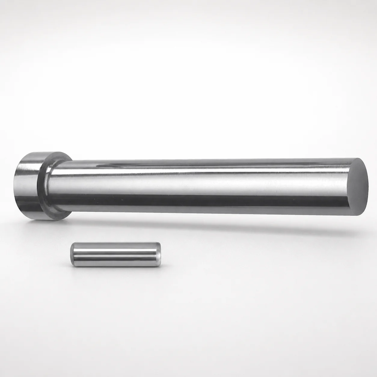
DAYTON Regular Center Dowel Punch Blanks for Heavy Load - Metric
DAYTON Regular Center Dowel Punch Blanks for Heavy Load - Metric are engineered for forming punch components with dependable center dowel guidance. Use these metric punch blanks when heavy-duty production and consistent alignment are critical.
- Center dowel hole layout supports stable punch alignment during press cycles
- Built for heavy-load applications to improve repeatable performance under strain
- Supports metric shank diameters D: 10 to 25 mm for flexible tooling builds
- Available in length range L: 80 to 130 mm to match standard punch holder setups
Specifications
5 configurations available
| D (Shank dia.) (mm) | L (Length) (mm) |
|---|---|
| 10 | 80 ~ 130 |
| 13 | 80 ~ 130 |
| 16 | 80 ~ 130 |
| 20 | 80 ~ 130 |
| 25 | 80 ~ 130 |
Product Guide
Application Scenarios+
These metric center dowel punch blanks are used inside injection mold tooling and progressive/punch press setups where a punch must maintain a stable center dowel location throughout repeated forming cycles. They are particularly suitable for automotive connector and terminal tooling, where alignment directly impacts part geometry and reduces flash or dimensional drift across high-volume runs.
For electronics housings and precision insert features, the heavy-load construction helps preserve consistent punch guidance under load, supporting repeatable outcomes in multi-station operations.
They are also a practical choice for medical device component tooling requiring controlled process stability. The variant’s compatibility with metric shank diameters (D: 10–25 mm) and a defined length range (L: 80–130 mm) makes it easier to standardize punch holder configurations while keeping center guidance dependable during press strokes.
Material & Process Details+
The provided specifications specify dimensional variants (D: 10, 13, 16, 20, 25 mm and L: 80–130 mm) but do not include a steel grade, hardness (HRC), or heat-treatment state. Therefore, material properties, wear resistance, toughness, and heat treatment (e.g., quenched & tempered or nitrided) cannot be stated from the input data.
When selecting a comparable center-dowel-guided punch blank for heavy-load applications, engineers typically balance wear resistance (to resist deformation at the punch working surface) with toughness (to avoid chipping under impact or misalignment). If multiple steels are offered for this series, confirm the intended grade and target hardness with the supplier before final tooling approval.
Sizing & Selection Guide+
Select the punch blank based on the mold/tooling center guidance requirements and the corresponding holder geometry. Match the shank diameter (D) to your punch system: available sizes are D = 10, 13, 16, 20, or 25 mm.
Then select the length (L) to fit the station depth and the punch holder setup. The series provides a fixed range of L = 80 to 130 mm.
- D match: Ensure the holder bushing/hole and the guide components are compatible with the selected shank diameter to maintain concentricity and guidance.
- L match: Verify total stack-up (holder length, wear parts allowance, and clearance) so the punch protrusion fits the cavity/feature depth.
- Tolerance/fit: Use the tooling’s standard fit class for dowel-guided punches; any mismatch can increase side load and reduce repeatability.
Dimensions listed as available are configurable by part variant (D and L), while all other geometry details are controlled by the series design.
Frequently Asked Questions
What shank diameters (D) are available for this heavy-load center dowel punch blank series?+
This series lists D = 10, 13, 16, 20, 25 mm as available shank diameter options.
Choose the diameter that matches your punch holder and guide bushing to maintain correct alignment around the center dowel location.
How do I choose the correct length (L) for a specific punch holder stack-up?+
The fixed length range available is L = 80 to 130 mm.
Confirm the combined stack-up of the punch holder, any backing plates, and wear allowances so the punch reaches the required forming/cutting depth without binding in the guide.
How does the center dowel layout help improve alignment during heavy-duty production?+
The design intent is to provide a stable center dowel hole layout that keeps punch guidance consistent through press cycles.
For heavy-load applications, that stability helps reduce alignment-related dimensional variation and supports repeatable performance under strain.
Is this suitable for tooling that requires stable guidance under strain, such as high-volume connector or terminal operations?+
Yes. The product description targets punch components where consistent alignment and robust performance are critical under heavy-load conditions.
Verify that your tooling’s required punch diameter is one of the listed options (D: 10–25 mm) and that the required punch length falls within L: 80–130 mm.
Related Products
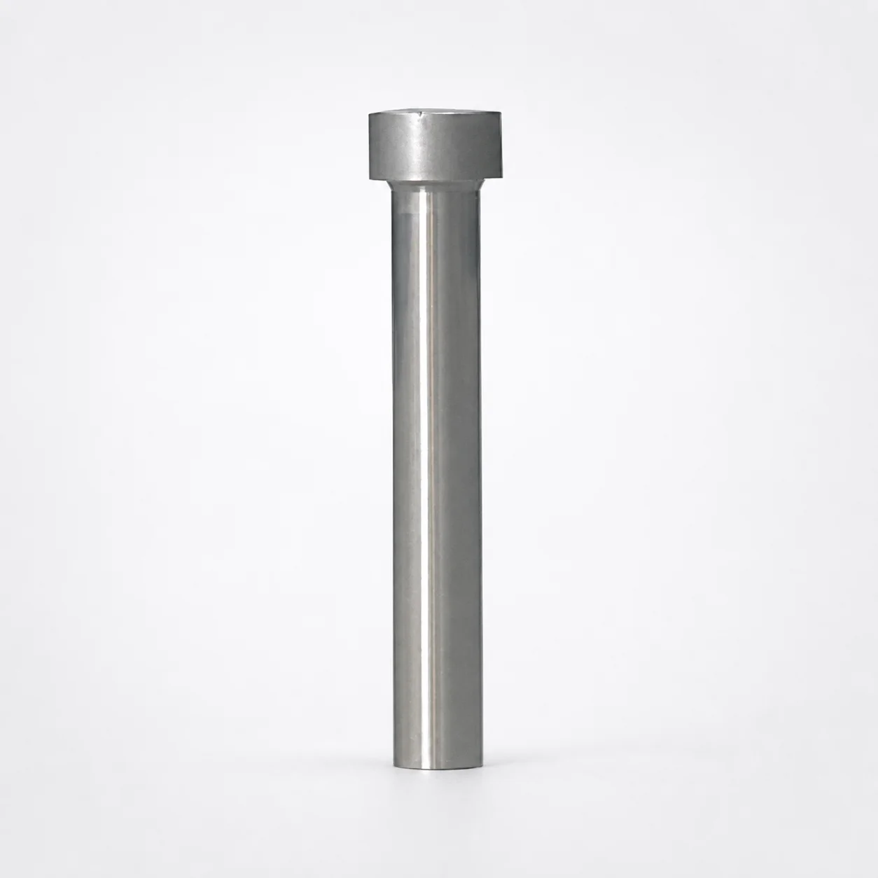
Ejector Punch Blanks (Blank, Standard)
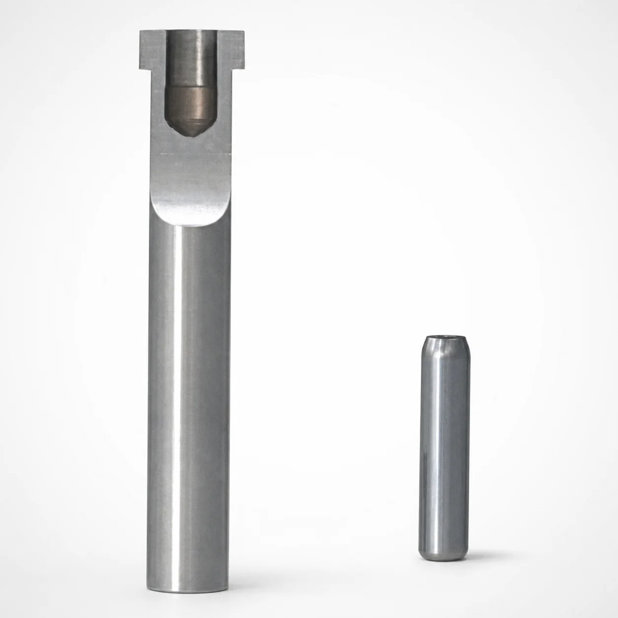
SKD11 Equivalent Steel Ejector Punch Blanks with Locating Dowel Hole
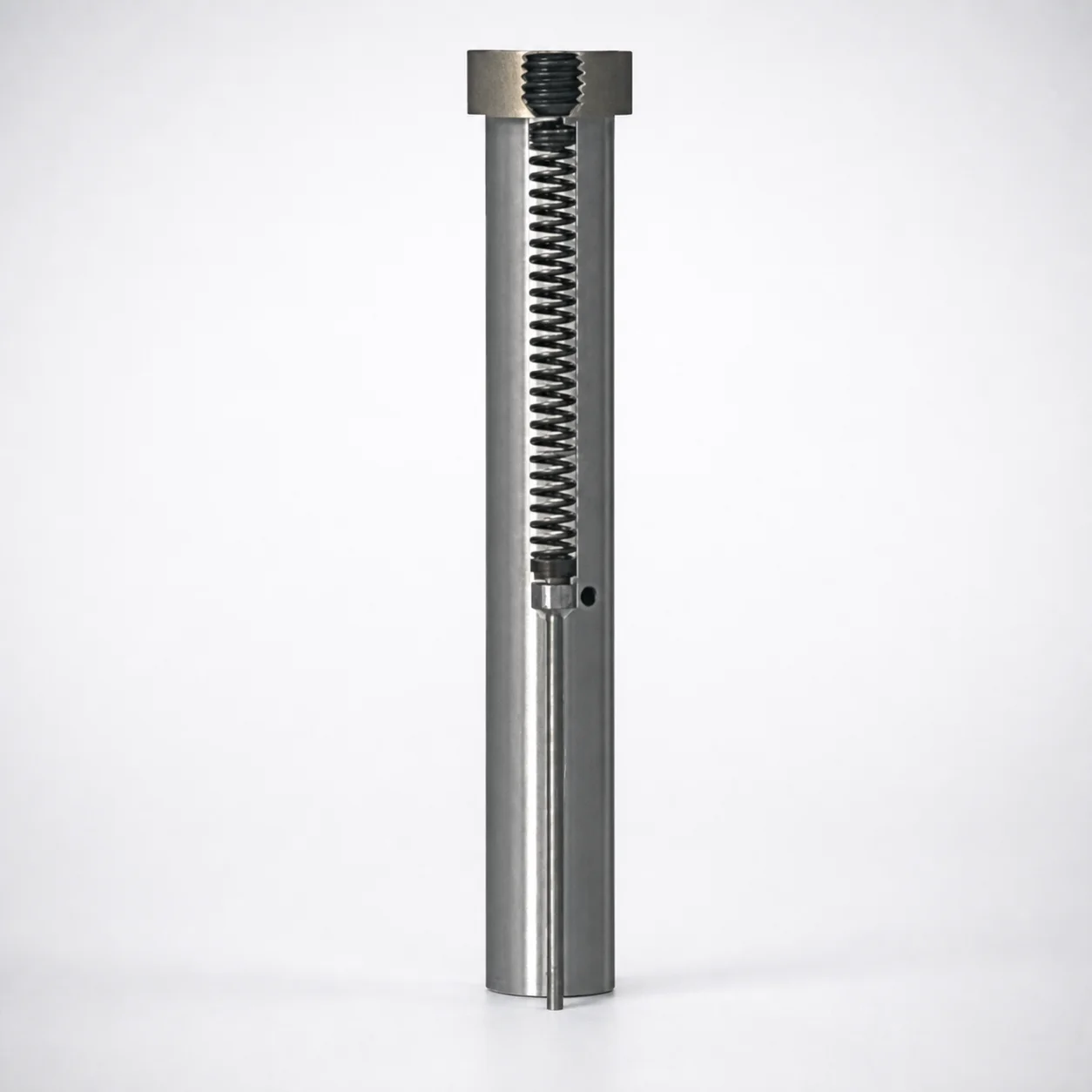
Large-Diameter Pin Type Ejector Punch Blanks
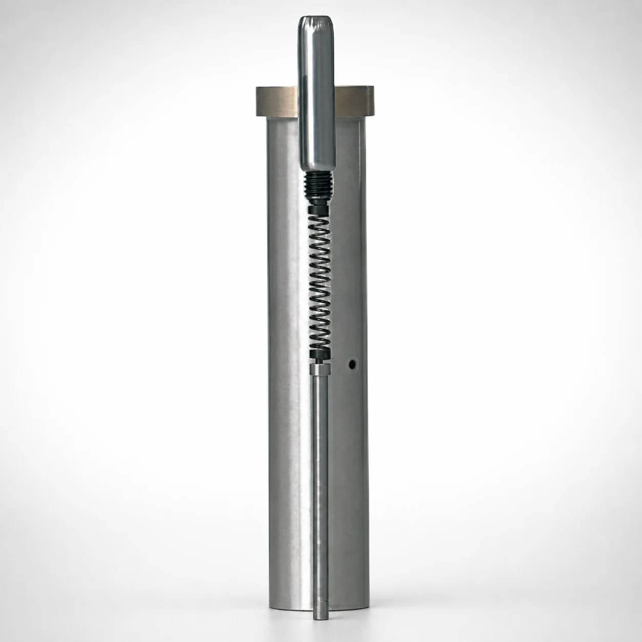
SKD11 Steel Ejector Punch Blank with Locating Dowel Hole (D2 Equivalent)
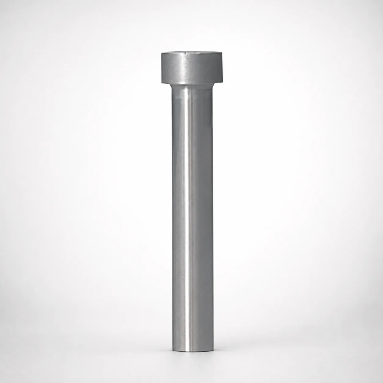
Heavy Load Punch Blanks - Metric (Diameters 10-25 mm)
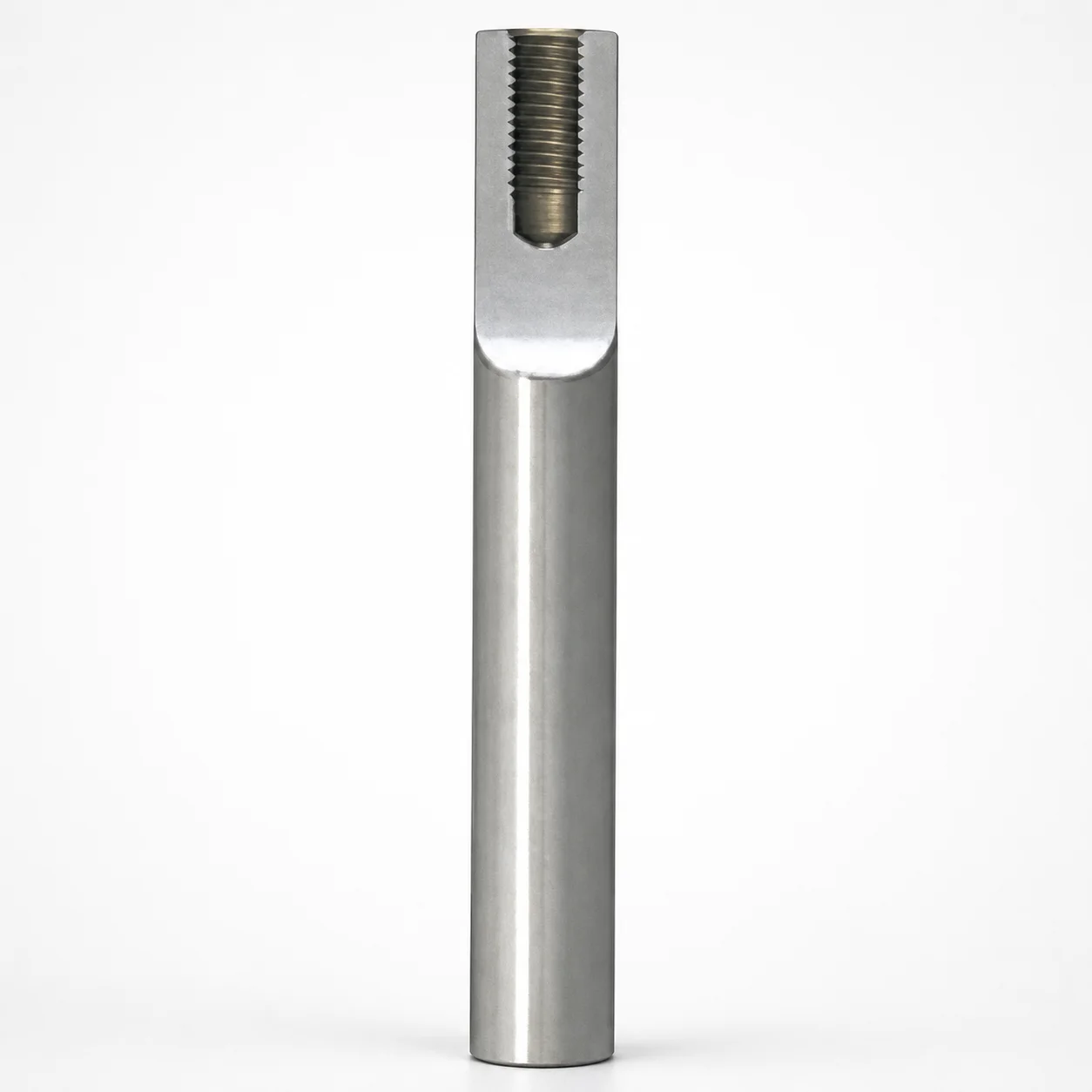
Metric Tapped Punch Blanks for Bolt-Fixed Punches
Need Custom Specifications?
Our engineering team can help with custom configurations, material selection, and volume pricing.