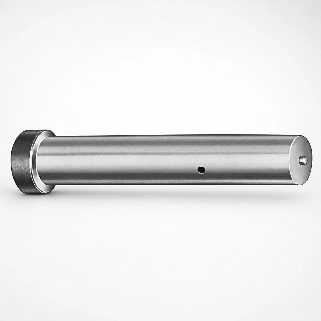
Ejector Punch Blanks - Metric with Center Dowel Hole
Ejector Punch Blanks - Metric with Center Dowel Hole are designed for accurate die spotting and stable guidance during punch operations. Select from PS, M2, or A2 steel blank options to match your production needs.
- Built-in center dowel hole supports repeatable punch positioning and alignment
- Material options including M2 steel and A2 steel for reliable cutting performance
- Designed for metric shank sizes with flexible diameter (D) selection
- Metric ejector punch blank format suitable for progressive and transfer die setups
Specifications
27 configurations available
| Material | D (Shank dia.) (mm) | L (Length) (mm) |
|---|---|---|
| A2 | 05 | 40 ~ 100 |
| M2 | 05 | 40 ~ 100 |
| PS | 05 | 40 ~ 100 |
| A2 | 06 | 40 ~ 100 |
| M2 | 06 | 40 ~ 100 |
| PS | 06 | 40 ~ 100 |
| A2 | 08 | 50 ~ 100 |
| M2 | 08 | 50 ~ 100 |
| PS | 08 | 50 ~ 100 |
| A2 | 10 | 50 ~ 100 |
| M2 | 10 | 50 ~ 100 |
| PS | 10 | 50 ~ 100 |
| A2 | 13 | 50 ~ 100 |
| M2 | 13 | 50 ~ 100 |
| PS | 13 | 50 ~ 100 |
| A2 | 16 | 50 ~ 100 |
| M2 | 16 | 50 ~ 100 |
| PS | 16 | 50 ~ 100 |
| A2 | 20 | 56 ~ 100 |
| M2 | 20 | 56 ~ 100 |
| PS | 20 | 56 ~ 100 |
| A2 | 25 | 56 ~ 100 |
| M2 | 25 | 56 ~ 100 |
| PS | 25 | 56 ~ 100 |
| A2 | 32 | 63 ~ 100 |
| M2 | 32 | 63 ~ 100 |
| PS | 32 | 63 ~ 100 |
Product Guide
Application Scenarios+
These metric ejector punch blanks are used inside progressive and transfer die tooling where punch-to-die alignment directly affects part quality. The center dowel hole provides die spotting and stable guidance, helping maintain repeatable positioning under cyclic press loads.
- Automotive and appliance progressive dies: When multiple stations must index precisely, the dowel-referenced blank improves punch alignment, reducing side-load and improving cycle-to-cycle consistency.
- Die spotting and ejector return assemblies: The blank format supports controlled punch movement and stable guidance, which is especially useful for ejector systems that need smooth, repeatable stroke behavior.
- General metal forming punch operations: Selecting M2 or A2 steel variants supports durable cutting performance for longer runs, while PS options can be chosen for cost-effective fabrication where wear demand is moderate.
Metric shank sizing and the provided D (5–32 mm) range make it straightforward to match common die layouts.
Material & Process Details+
Available steels are PS, M2, and A2, selected to balance hardness, wear resistance, and toughness for punch blank service. For high-wear punch applications, M2 (high-speed steel) is typically chosen for strong wear resistance under cutting action; A2 is often selected when you need a tough tool steel with good dimensional stability after heat treatment.
- M2: Generally suited for tougher wear conditions; heat treated to a high hardness level for cutting durability (commonly in the mid-to-high HRC range depending on supplier process).
- A2: Usually hardened and tempered or quenched/tempered to achieve high hardness while maintaining improved toughness compared with very brittle grades.
- PS: A lower-alloy option used when cost and ease of fabrication matter, providing adequate performance for moderate wear demands.
In practice, hardness and wear resistance improve with higher-carbide/appropriate heat treatment, but increased hardness can reduce impact toughness—so select the grade that matches your loading and expected cycles.
Sizing & Selection Guide+
To select the correct ejector punch blank, match the shank diameter (D) and the overall length (L) to your die’s punch guide and support requirements. This series covers D = 5–32 mm, so choose the diameter that fits your punch bore/guide size with the intended clearance for sliding guidance.
- Choose diameter (D): Select the exact size within 5 ~ 32 mm to align with your guide bushing or locating features.
- Choose length (L): Length options are provided as ranges: 40–100 mm, 50–100 mm, 56–100 mm, and 63–100 mm. Pick the minimum length that provides required working stroke coverage plus safe overtravel margins.
- Account for center dowel hole referencing: Ensure the dowel hole alignment interfaces correctly with your die spotting/guidance scheme so punch positioning remains repeatable.
Use your mold’s guide tolerances to confirm fit; tighter guidance improves alignment but increases risk of binding if clearances are too small.
Frequently Asked Questions
Which steel grade (PS, M2, or A2) is best for long-run progressive die punch blanks?+
For higher wear demand and more abrasive punch conditions, M2 is typically selected due to its strong cutting/wear performance. A2 is commonly chosen when you need a balance of hardness and toughness after heat treatment. PS is a suitable option for moderate wear loads where fabrication cost or flexibility is prioritized.
How do I choose the correct shank diameter (D) for the ejector punch guide system?+
Select D (5–32 mm) to match your die’s punch bore/guide bushing diameter. Use the intended clearance for guided sliding so the center dowel hole can maintain repeatable positioning without causing bind under load. If your guide is tighter, confirm tool-to-bore tolerances to avoid galling or frictional drag.
What length (L) range should I use for my required stroke and overtravel?+
This series provides L as ranges: 40–100, 50–100, 56–100, and 63–100 mm. Choose the shortest length that still covers your effective working stroke and provides safe overtravel margins for assembly. Validate against your die layout so the punch remains guided throughout the stroke.
Does the center dowel hole affect die spotting repeatability in transfer die applications?+
Yes. The built-in center dowel hole is intended to reference die spotting and maintain stable guidance, improving punch-to-die alignment from cycle to cycle. In transfer die setups where stations must index accurately, this dowel-referenced positioning helps reduce misalignment from cumulative tolerances.
Can this blank be used across different progressive/transfer die configurations with metric sizing?+
The blank format is designed for metric shank sizing, with D = 5–32 mm and selectable L ranges up to 100 mm. This makes it compatible with common metric die designs, provided your guide bushing and locating features match the selected diameter and length. Confirm that your die’s dowel/spotting geometry aligns with the center dowel hole interface.
Related Products
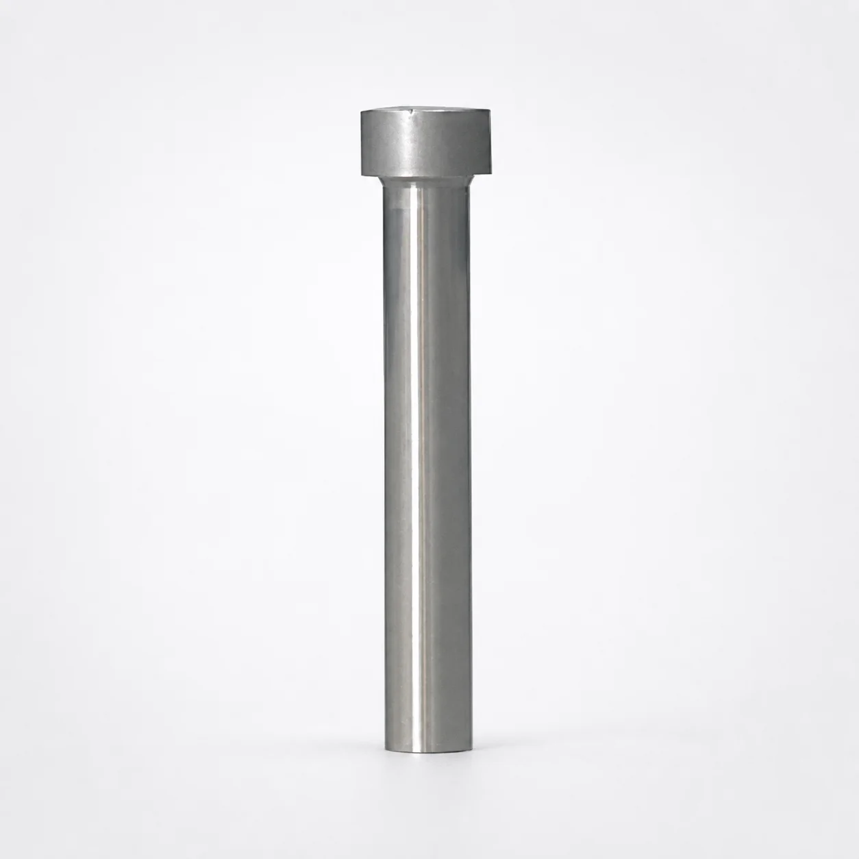
Ejector Punch Blanks (Blank, Standard)
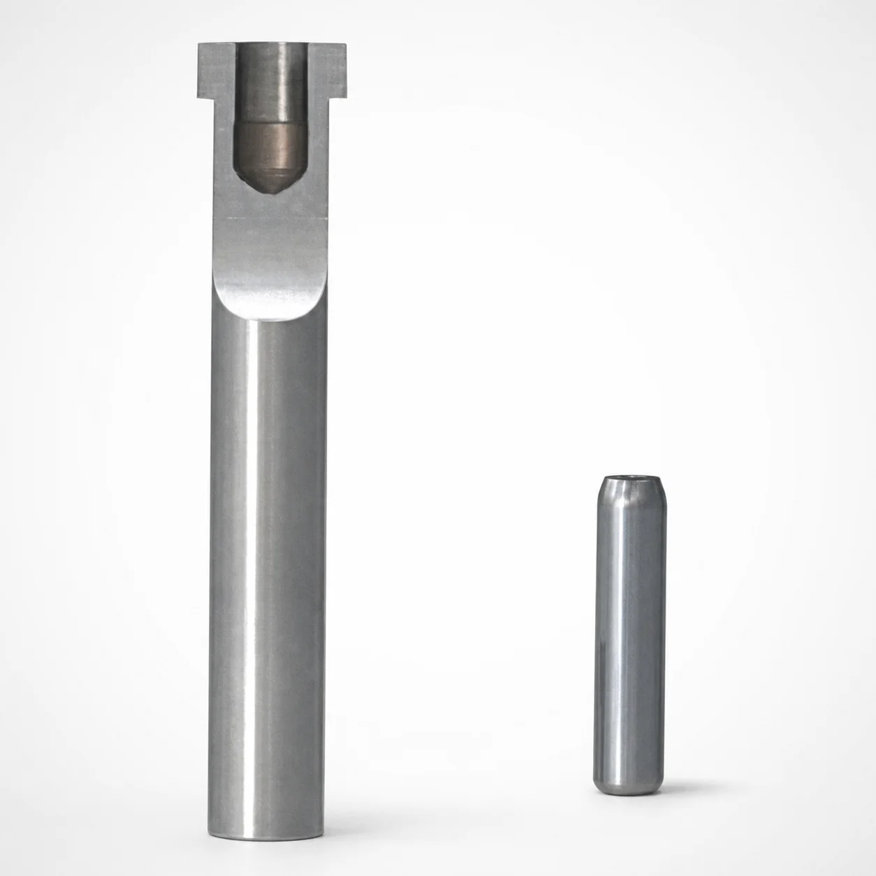
SKD11 Equivalent Steel Ejector Punch Blanks with Locating Dowel Hole
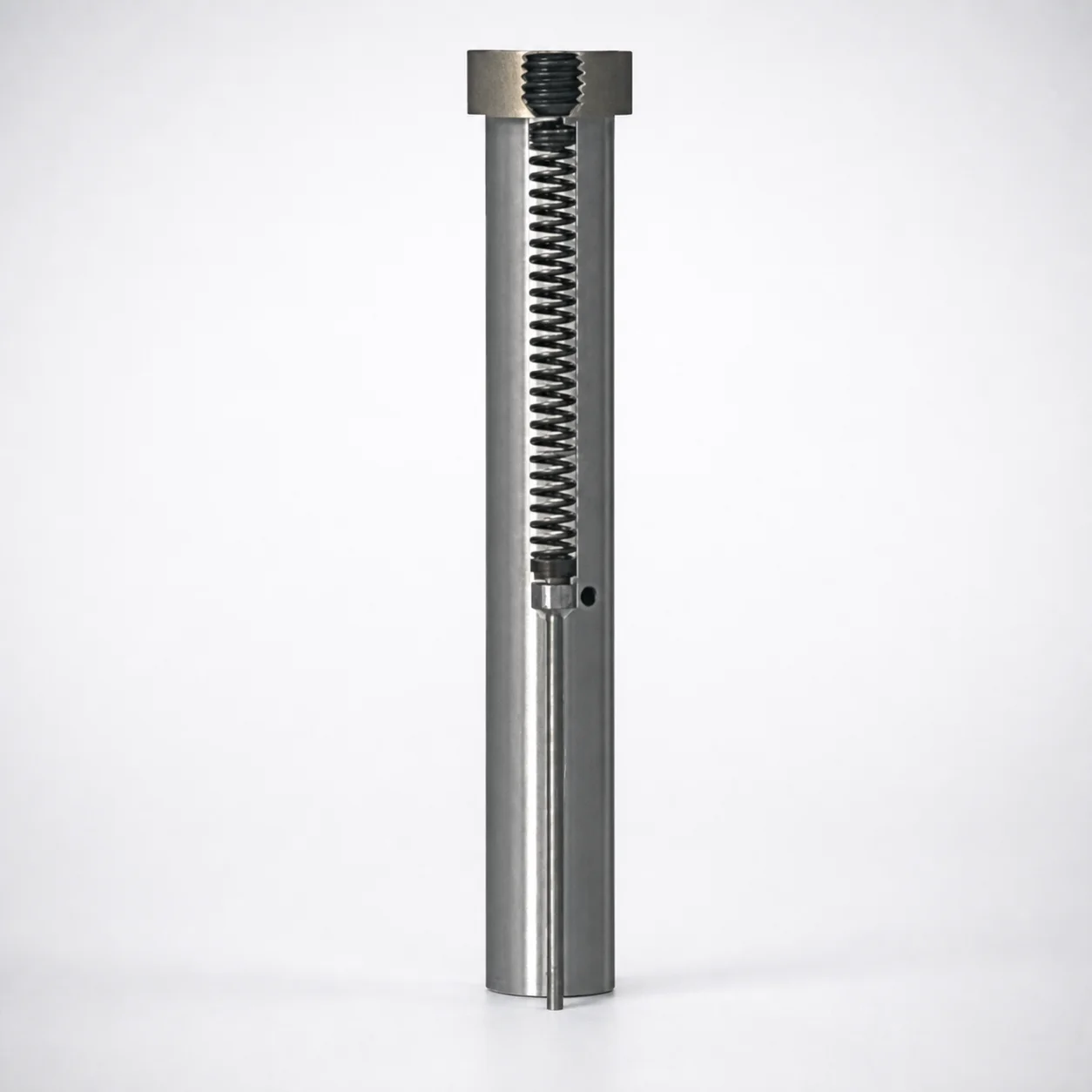
Large-Diameter Pin Type Ejector Punch Blanks
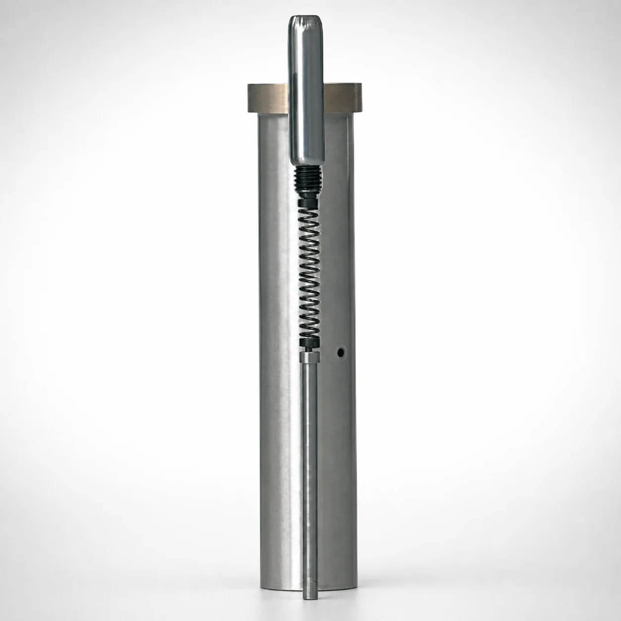
SKD11 Steel Ejector Punch Blank with Locating Dowel Hole (D2 Equivalent)
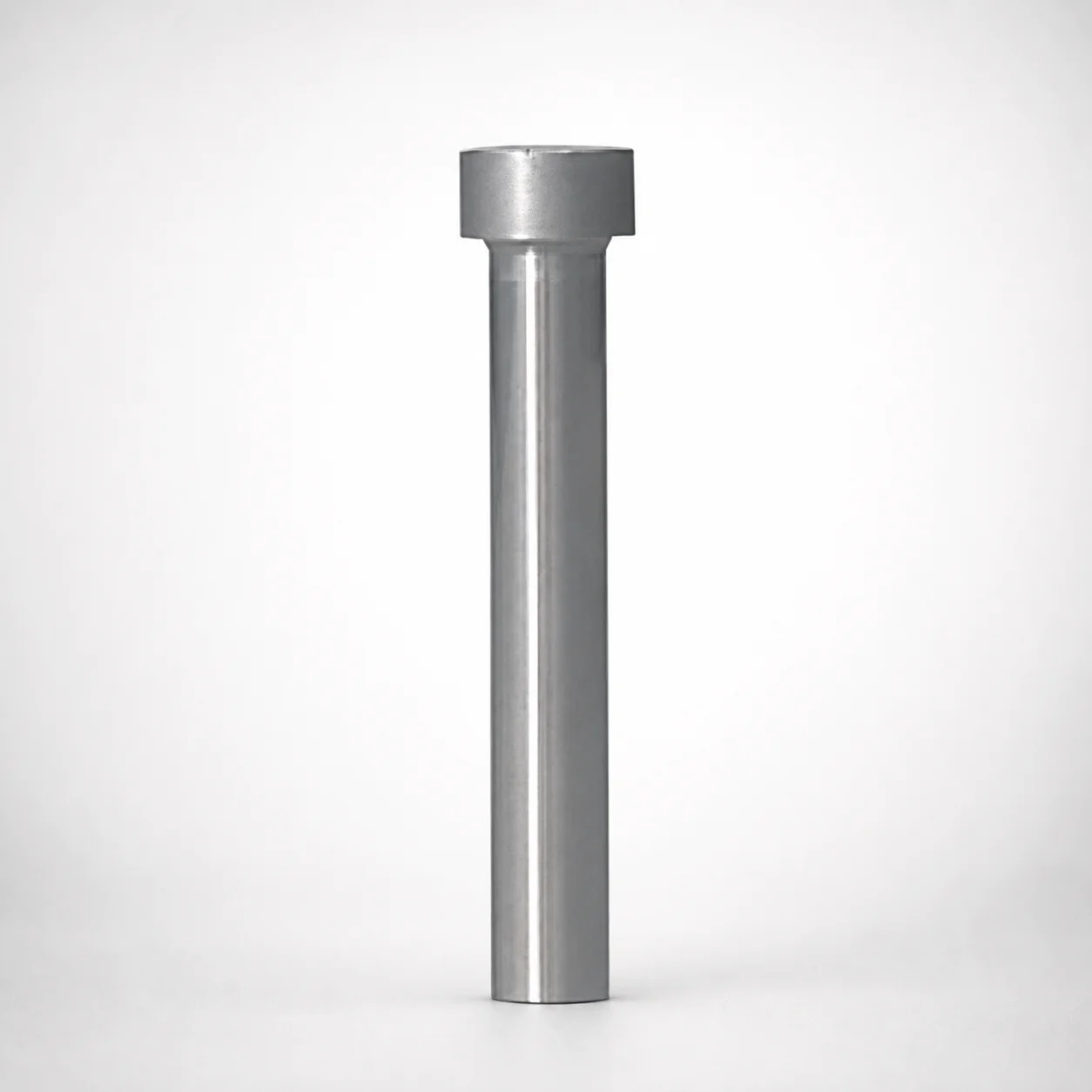
Heavy Load Punch Blanks - Metric (Diameters 10-25 mm)
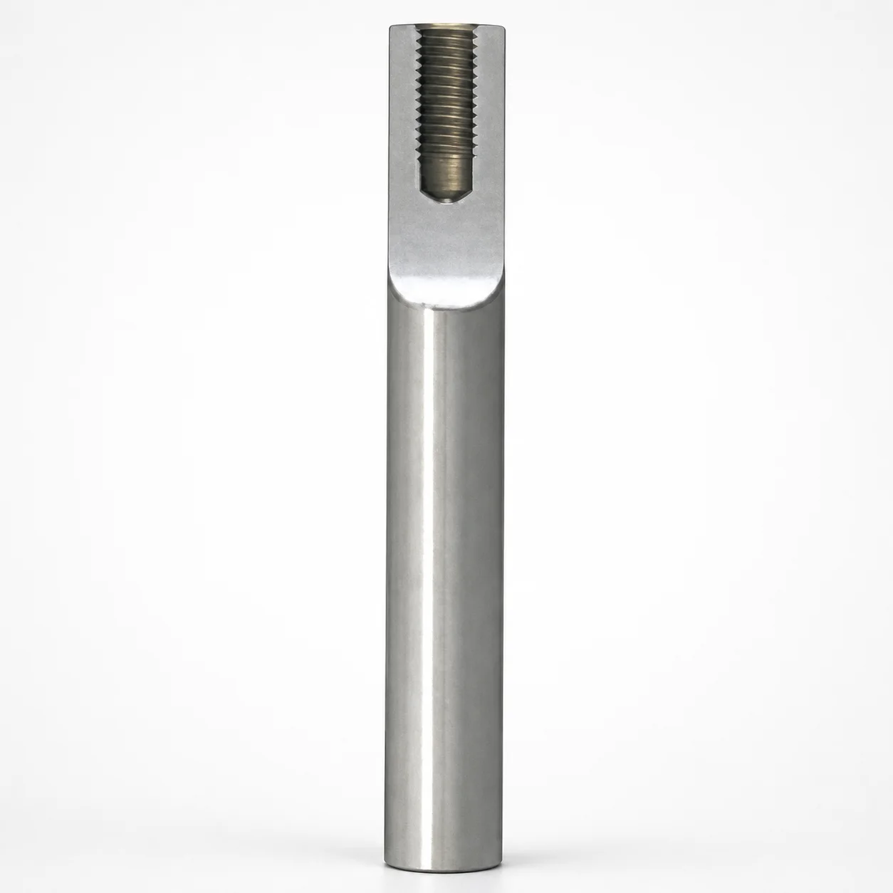
Metric Tapped Punch Blanks for Bolt-Fixed Punches
Need Custom Specifications?
Our engineering team can help with custom configurations, material selection, and volume pricing.