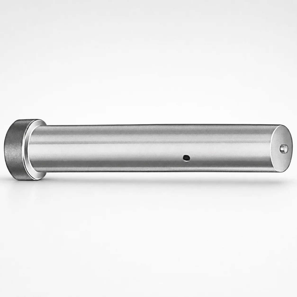
Inch Ejector Punch Blanks
Inch ejector punch blanks (DAYTON) are made for building punches used in progressive dies and forming applications, offering dependable blank performance before final grinding and finishing. Material options help balance wear resistance and machining.
- Inch punch blank format designed for punch fabrication and final machining
- Tool steel options include M2 or A2 for durable cutting tool service
- Available coded point length selections support consistent punch geometry
- Suitable for ejector punch production in inch-based die builds
Specifications
46 configurations available
| Material | D (Shank dia.) (in) | Standard [S] Point Length B & L (Length) (coded inch) | Alternate [B] Point Length B & L (Length) (coded inch) | Alternate [C] Point Length B & L (Length) (coded inch) | Alternate [D] Point Length B & L (Length) (coded inch) | Alternate [E] Point Length B & L (Length) (coded inch) |
|---|---|---|---|---|---|---|
| A2 | 18 (0.1875") | - | 150 ~ 400 | - | - | - |
| M2 | 18 (0.1875") | - | 150 ~ 400 | - | - | - |
| A2 | 18 (0.1875") | 150 ~ 400 | - | - | - | - |
| M2 | 18 (0.1875") | 150 ~ 400 | - | - | - | - |
| A2 | 25 (0.2500") | - | 150 ~ 400 | - | - | - |
| M2 | 25 (0.2500") | - | 150 ~ 400 | - | - | - |
| A2 | 25 (0.2500") | 150 ~ 400 | - | - | - | - |
| M2 | 25 (0.2500") | 150 ~ 400 | - | - | - | - |
| A2 | 31 (0.3125") | - | 150 ~ 600 | - | - | - |
| M2 | 31 (0.3125") | - | 150 ~ 600 | - | - | - |
| A2 | 31 (0.3125") | - | - | 175 ~ 600 | - | - |
| M2 | 31 (0.3125") | - | - | 175 ~ 600 | - | - |
| A2 | 31 (0.3125") | 150 ~ 600 | - | - | - | - |
| M2 | 31 (0.3125") | 150 ~ 600 | - | - | - | - |
| A2 | 37 (0.3750") | - | 175 ~ 625 | - | - | - |
| M2 | 37 (0.3750") | - | 175 ~ 625 | - | - | - |
| A2 | 37 (0.3750") | - | - | 175 ~ 625 | - | - |
| M2 | 37 (0.3750") | - | - | 175 ~ 625 | - | - |
| A2 | 37 (0.3750") | 175 ~ 625 | - | - | - | - |
| M2 | 37 (0.3750") | 175 ~ 625 | - | - | - | - |
| A2 | 43 (0.4375") | - | - | 200 ~ 625 | - | - |
| M2 | 43 (0.4375") | - | - | 200 ~ 625 | - | - |
| A2 | 43 (0.4375") | 200 ~ 625 | - | - | - | - |
| M2 | 43 (0.4375") | 200 ~ 625 | - | - | - | - |
| A2 | 50 (0.5000") | - | - | 200 ~ 625 | - | - |
| M2 | 50 (0.5000") | - | - | 200 ~ 625 | - | - |
| A2 | 50 (0.5000") | 200 ~ 625 | - | - | - | - |
| M2 | 50 (0.5000") | 200 ~ 625 | - | - | - | - |
| A2 | 62 (0.6250") | - | - | - | 200 ~ 625 | - |
| M2 | 62 (0.6250") | - | - | - | 200 ~ 625 | - |
| A2 | 62 (0.6250") | 200 ~ 625 | - | - | - | - |
| M2 | 62 (0.6250") | 200 ~ 625 | - | - | - | - |
| A2 | 75 (0.7500") | - | - | - | 225 ~ 625 | - |
| M2 | 75 (0.7500") | - | - | - | 225 ~ 625 | - |
| A2 | 75 (0.7500") | 225 ~ 625 | - | - | - | - |
| M2 | 75 (0.7500") | 225 ~ 625 | - | - | - | - |
| A2 | 87 (0.8750") | - | - | - | 250 ~ 650 | - |
| M2 | 87 (0.8750") | - | - | - | 250 ~ 650 | - |
| A2 | 87 (0.8750") | - | - | - | - | 250 ~ 650 |
| M2 | 87 (0.8750") | - | - | - | - | 250 ~ 650 |
| A2 | 87 (0.8750") | 250 ~ 650 | - | - | - | - |
| M2 | 87 (0.8750") | 250 ~ 650 | - | - | - | - |
| A2 | 100 (1.0000") | - | - | - | - | 250 ~ 650 |
| M2 | 100 (1.0000") | - | - | - | - | 250 ~ 650 |
| A2 | 100 (1.0000") | 250 ~ 650 | - | - | - | - |
| M2 | 100 (1.0000") | 250 ~ 650 | - | - | - | - |
Product Guide
Application Scenarios+
In injection mold and tool-and-die environments, these inch ejector punch blanks serve as the starting geometry for ejector punches and other punch-style components that are finish-ground after heat treatment. They are commonly used in progressive dies where consistent punch profiles are critical for repeatable part forming and stripping.
For precision forming and piercing stations, the blank format supports final machining to match specific die cavity/core layouts, then grinding to achieve surface finish targets. The provided coded point length selections help streamline design variation control across multi-cavity tooling builds.
When tooling includes ejector systems in inch-based die builds, the shank diameter range supports scalable ejector punch sizing while keeping the punch-to-holder interface consistent. The availability of A2 or M2 tool steel makes this variant suited to balance wear resistance against machining and toughness requirements.
- Progressive die ejector and forming punch fabrication (final grind-ready blanks)
- Finish machining for station-specific geometry and part stripping performance
- Inch-based tooling builds needing shank diameter flexibility and coded point lengths
Material & Process Details+
This product is available in two tool steel options: A2 and M2. Both are commonly used for cutting/tooling applications where wear resistance is needed, but they differ in typical performance emphasis.
- A2: an air-hardening tool steel (often supplied quenched and tempered or pre-hardened, depending on supplier process). It generally offers a strong balance of toughness and wear resistance for punch and forming work.
- M2: high-speed steel (HSS, typically designed for greater hot hardness and wear endurance). Compared with A2, M2 is often selected when abrasive or high-load cutting/stripping demands more wear resistance.
Since hardness and heat-treatment state can vary by supply condition, verify the receiving hardness/spec sheet for your exact build. As a rule of thumb for selection, M2 tends to improve wear resistance at the cost of harder-to-machine behavior, while A2 supports improved toughness/machinability trade-offs for many tool-and-die workflows.
Sizing & Selection Guide+
Select sizing from the provided inch ranges to match the punch shank diameter (D) and coded point length requirements for your die insert and punch holder interface.
- Shank diameter D (in): 18 ~ 100. Choose the diameter that matches your punch guide/bushing and ensures proper fit for alignment under load.
- Point length B & L (coded inch) is offered in multiple coded range families: 150 ~ 400, 150 ~ 600, 175 ~ 625, 200 ~ 625, 225 ~ 625, 250 ~ 650 depending on the Alternate code.
To match mold cavity/core requirements, first determine the required working length from your drawing (stack height from holder seat to cutting/working face). Then choose the closest coded point length range (e.g., “E: 250 ~ 650” or other listed alternates) to reduce rework in final grinding.
For fit and interchangeability, confirm the required clearance and tolerances between the punch shank and guide components; use your final grinding allowances to avoid interference at assembly.
Frequently Asked Questions
Which steel option (A2 vs M2) should I choose for ejector punch blanks used in progressive dies?+
How do I match the coded point length ranges (B & L) to the working length my tool requires?+
What shank diameter range is available for these inch ejector punch blanks?+
Do the Alternate point-length codes (B/C/D/E) indicate different point geometries or only length range options?+
Are these blanks intended to be finish-ground after heat treatment for tool-and-die production?+
Related Products
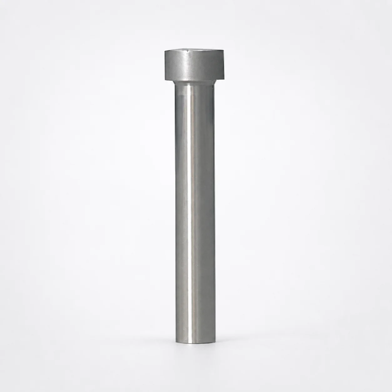
Ejector Punch Blanks (Blank, Standard)
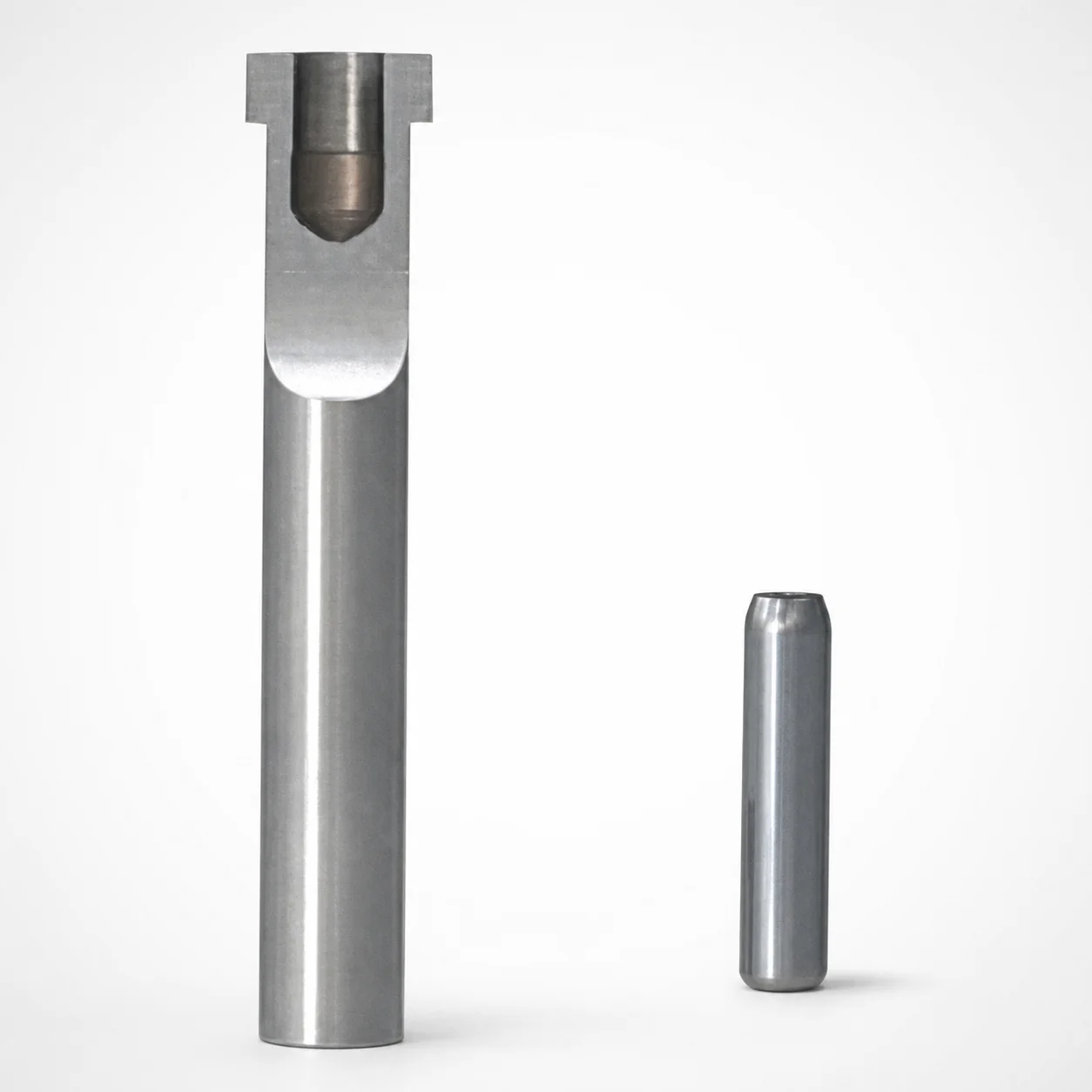
SKD11 Equivalent Steel Ejector Punch Blanks with Locating Dowel Hole
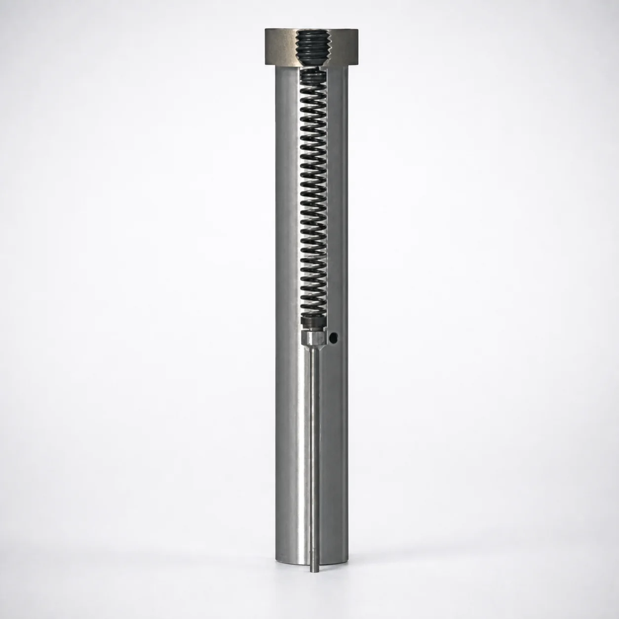
Large-Diameter Pin Type Ejector Punch Blanks
SKD11 Steel Ejector Punch Blank with Locating Dowel Hole (D2 Equivalent)
Heavy Load Punch Blanks - Metric (Diameters 10-25 mm)
Metric Tapped Punch Blanks for Bolt-Fixed Punches
Need Custom Specifications?
Our engineering team can help with custom configurations, material selection, and volume pricing.