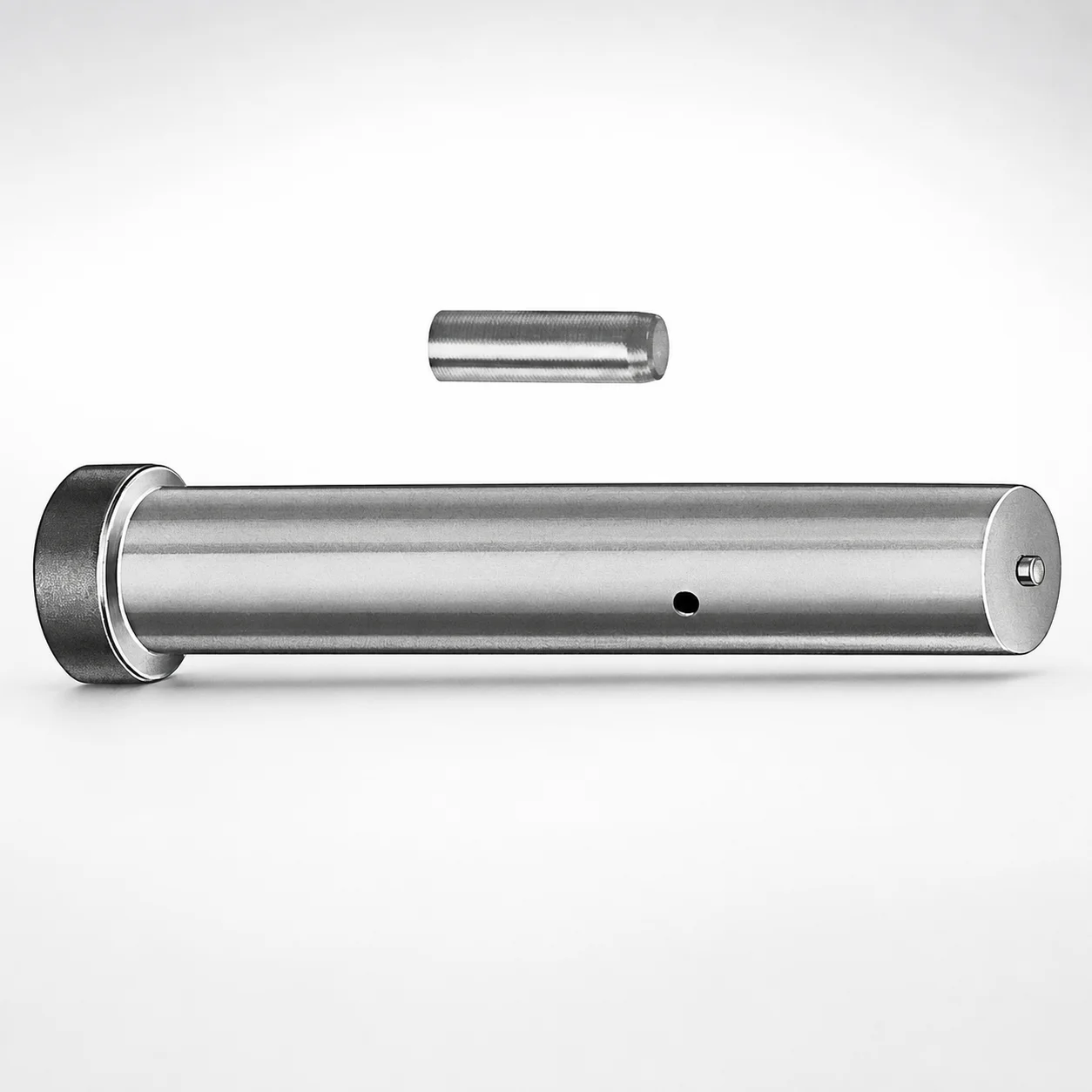
Center Dowel Ejector Punch Blanks - Metric
Center Dowel Ejector Punch Blanks - Metric (M2 or A2 steel) are precision die components designed to support reliable center guiding and ejection alignment in punch and ejector systems. These metric blanks help standardize part manufacturing for predictable press performance.
- Center dowel style blank for consistent locating in die assemblies
- M2 or A2 steel base material for durable, wear-tolerant punch performance
- Supports shank diameters from 10 to 32 mm for flexible die design
- Metric length range 71 to 130 mm to match common ejector layouts
Specifications
12 configurations available
| Material | D (Shank dia.) (mm) | L (Length) (mm) |
|---|---|---|
| A2 | 10 | 71 ~ 130 |
| M2 | 10 | 71 ~ 130 |
| A2 | 13 | 71 ~ 130 |
| M2 | 13 | 71 ~ 130 |
| A2 | 16 | 71 ~ 130 |
| M2 | 16 | 71 ~ 130 |
| A2 | 20 | 71 ~ 130 |
| M2 | 20 | 71 ~ 130 |
| A2 | 25 | 71 ~ 130 |
| M2 | 25 | 71 ~ 130 |
| A2 | 32 | 71 ~ 130 |
| M2 | 32 | 71 ~ 130 |
Product Guide
Application Scenarios+
Center dowel style ejector punch blanks are used in punch and ejector tooling where alignment directly affects stripping stability, part finish, and dimensional consistency. In automotive connector or terminal die sets, these blanks support stable guiding between the moving punch side and stationary die components, helping maintain concentricity during high-cycle ejection.
For appliance and stamped metal components, the metric shank options (10 to 32 mm) allow engineers to match the center guidance scheme used in standard ejector layouts. The specified length window (71 to 130 mm) supports typical ejector stroke packaging while keeping the punch guided through the die.
- M2 or A2 steel selection supports durable performance under sliding contact and intermittent shock during ejection.
- Use a center dowel locating blank when your die set requires repeatable centerline alignment for punch-to-die fit.
Material & Process Details+
This series is supplied in either A2 or M2 steel, both suited to punch blank applications where guiding surfaces must resist wear while tolerating the mechanical loads of ejection.
- A2 tool steel: typically supplied in the hardened condition and selected for a balance of toughness and wear resistance, helping reduce chipping risk during interrupted cutting or ejector impacts.
- M2 high-speed steel: commonly chosen when higher hot wear resistance and longer life are required at elevated interface temperatures. It generally provides stronger wear performance, with a trade-off of slightly lower toughness compared with tougher tool steels.
Because heat treatment depends on the specific grade and hardness target, final hardness is controlled by the manufacturer’s process to achieve the intended wear/toughness balance for die set guiding and ejection alignment.
Sizing & Selection Guide+
Select the blank using the shank diameter (D) and length (L) to match your die’s center guidance and ejector layout. The available shaft diameter options are D = 10, 13, 16, 20, 25, or 32 mm.
Choose L = 71 to 130 mm based on the stack-up from the moving plate to the guided work zone, including any support bushings and adjustment clearances. A correct length prevents over-compression at bottom-out and avoids insufficient guide engagement during ejection.
- Match D to the centerline bore or locating feature diameter in your guide system for proper fit and concentricity.
- Keep clearance requirements in mind: guiding components should allow reliable motion without binding, while maintaining alignment under load.
- Because L is fixed by the provided range (no per-length customization stated), select the closest length that fits your ejector stroke packaging.
Frequently Asked Questions
Which steel grade (A2 vs M2) is better for ejector alignment blanks in die sets?+
How do I choose the shank diameter (D) for the center guiding in a punch/ejector system?+
What length (L) range should I use when designing ejector stroke and guide engagement?+
Does the metric center dowel ejector punch blank fit standard die set layouts?+
What is the main function of using a center dowel style ejector punch blank in tooling?+
Related Products
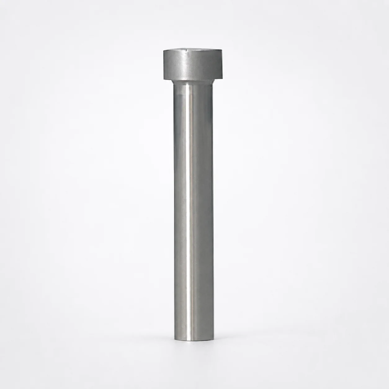
Ejector Punch Blanks (Blank, Standard)
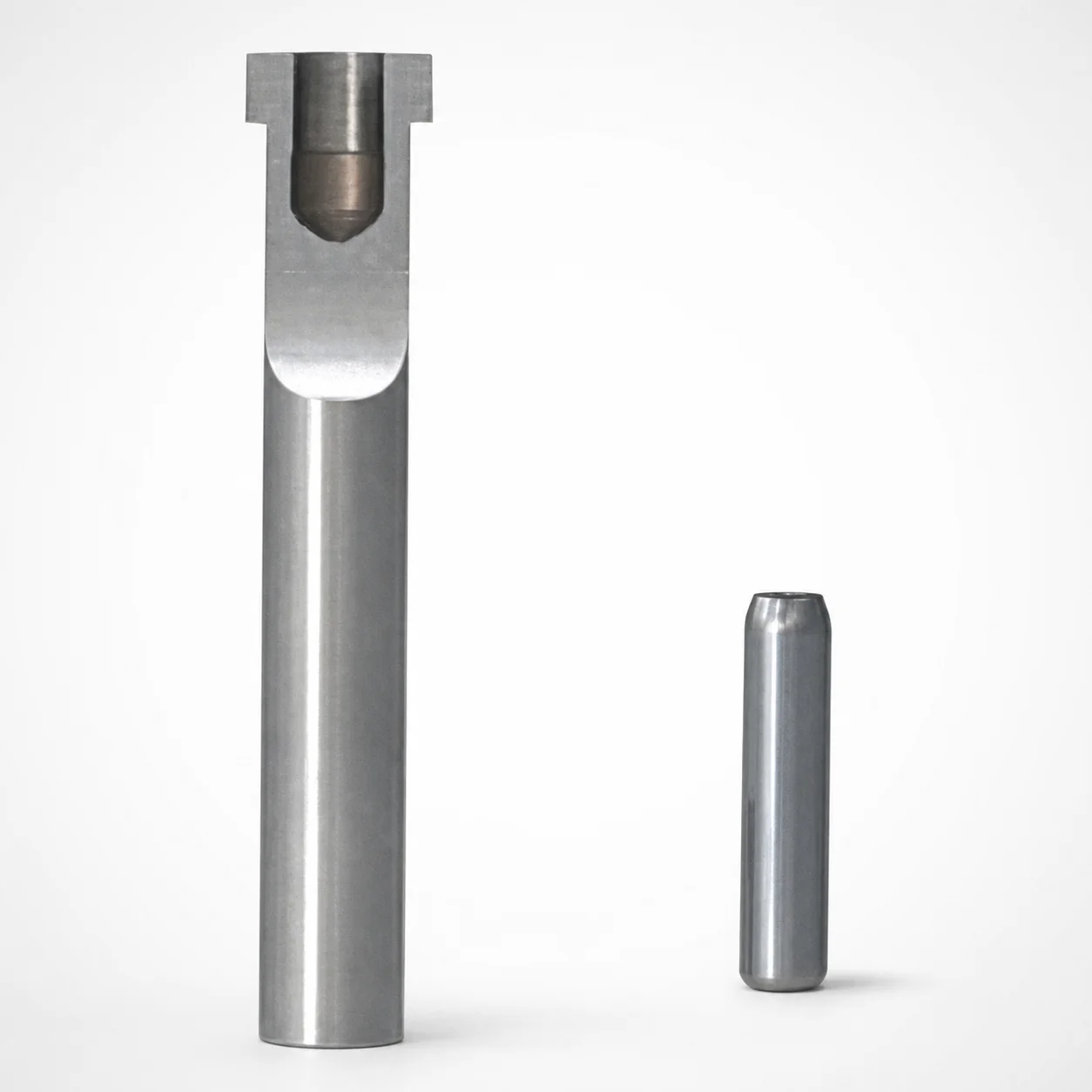
SKD11 Equivalent Steel Ejector Punch Blanks with Locating Dowel Hole
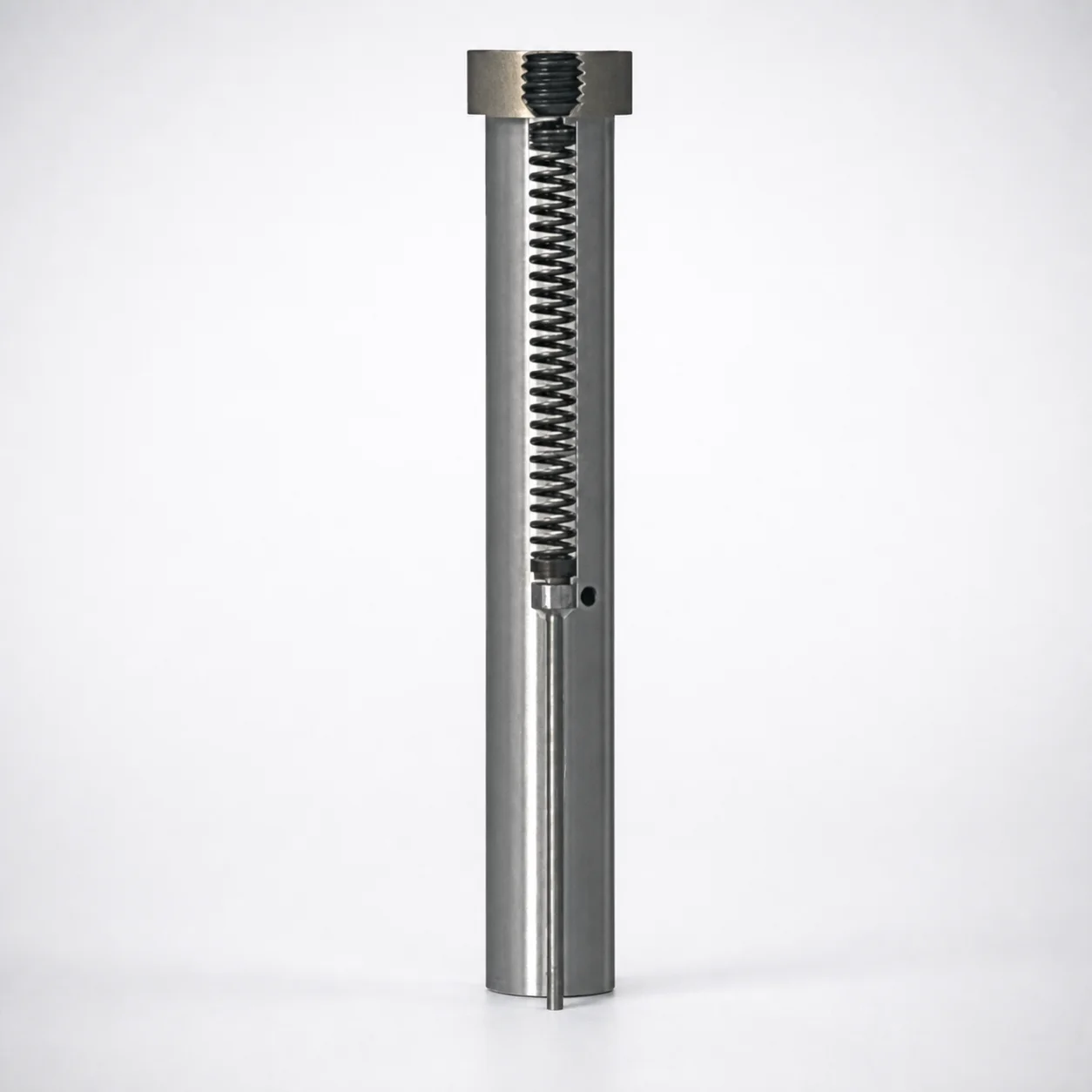
Large-Diameter Pin Type Ejector Punch Blanks
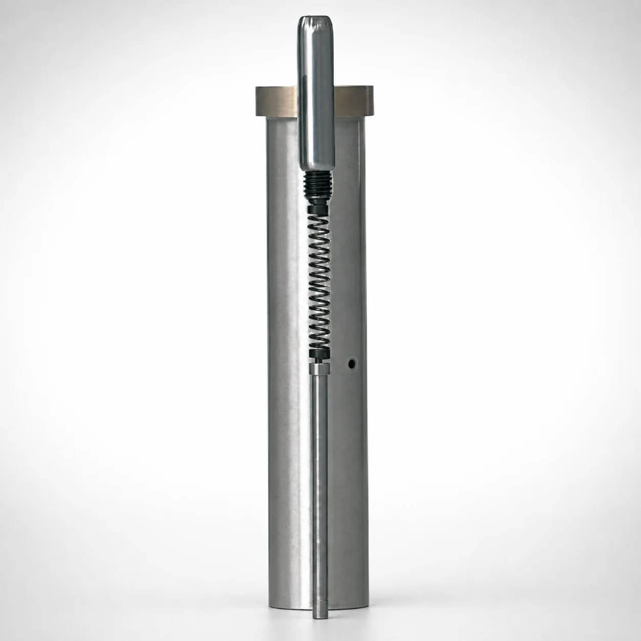
SKD11 Steel Ejector Punch Blank with Locating Dowel Hole (D2 Equivalent)
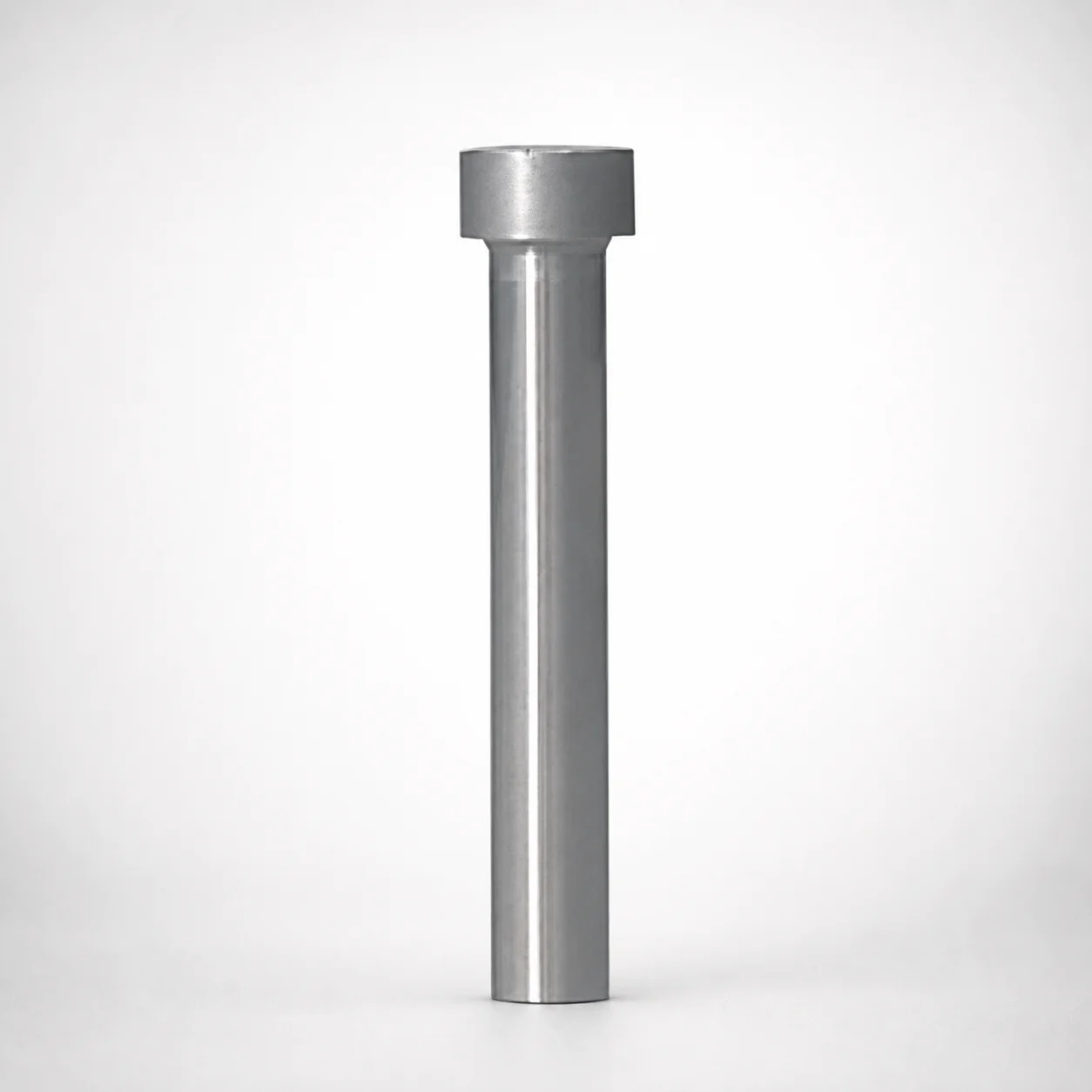
Heavy Load Punch Blanks - Metric (Diameters 10-25 mm)
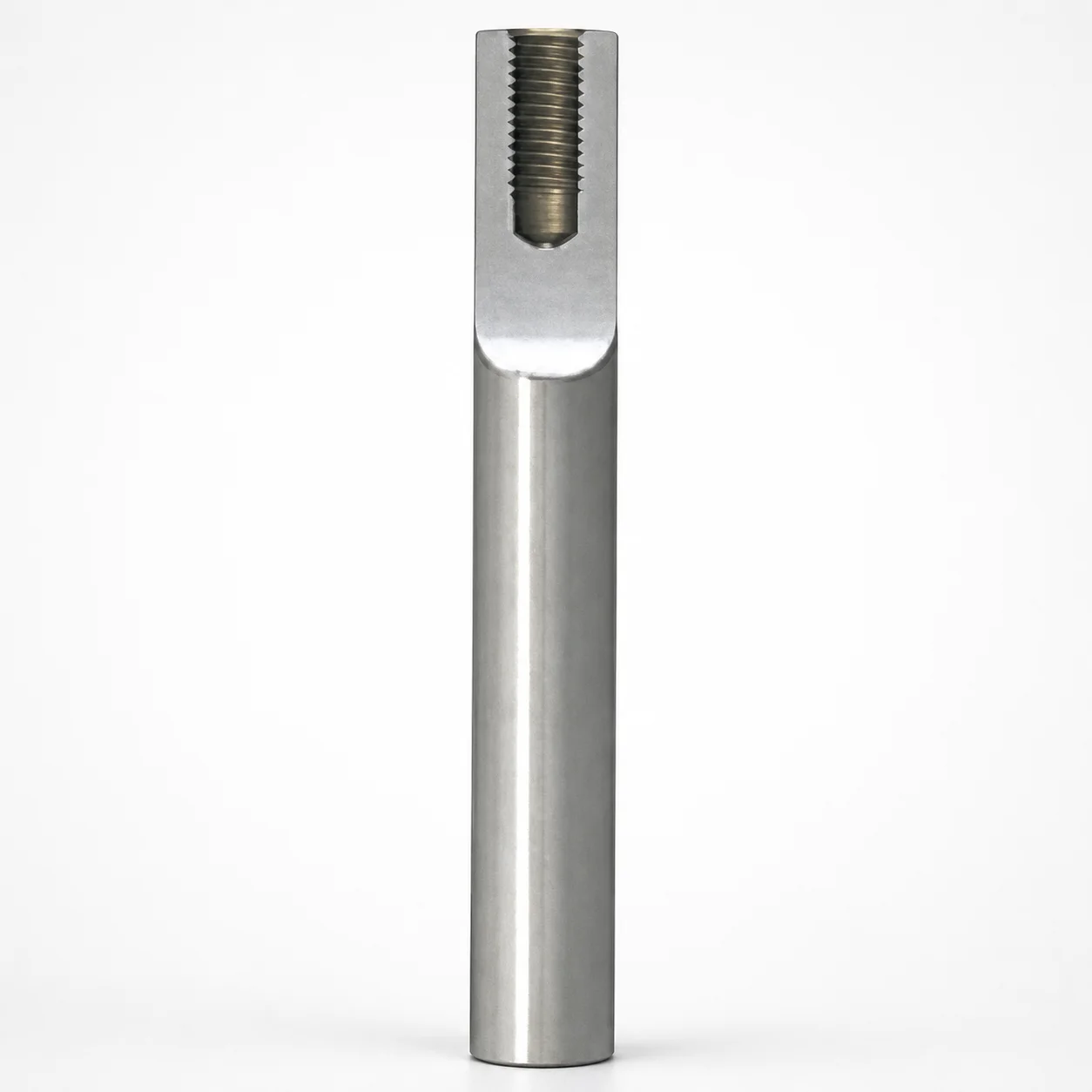
Metric Tapped Punch Blanks for Bolt-Fixed Punches
Need Custom Specifications?
Our engineering team can help with custom configurations, material selection, and volume pricing.