Leader Pins
Guide pins that align mold halves during close — available in straight, stepped, oil-free, and guiding assist configurations for every mold design.
Leader Pins Categories
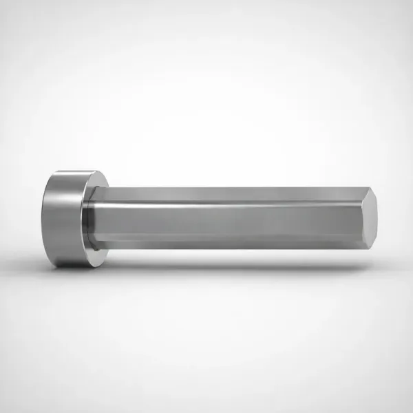
Straight Leader Pins
Standard cylindrical guide pins for general-purpose mold alignment. The most widely used type, available in JIS and DIN standards.
View Products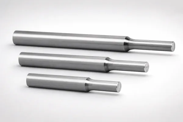
Stepped Leader Pins
Guide pins with diameter transitions for multi-plate molds and three-plate designs where different plate thicknesses require stepped engagement.
View Products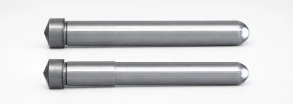
Guiding Assist Pins
Secondary guide pins positioned at the outer edges of large mold plates to provide additional alignment support and reduce plate deflection.
View Products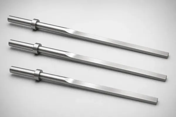
Oil-Free Leader Pins
Self-lubricating guide pins with embedded solid lubricant. Eliminate oil contamination for cleanroom, food-grade, and medical mold applications.
View ProductsHow to Choose the Right Leader Pin Type
Leader pin selection depends on your mold structure, plate count, and operating environment. Follow this two-step process to identify the right type.
Step 1: Match Your Mold Structure
| Selection Criteria | Straight | Stepped | Guiding Assist | Oil-Free |
|---|---|---|---|---|
| Mold Type | Two-plate standard molds | Three-plate molds, multi-plate stacks | Large molds (>500mm), high-precision molds | Cleanroom, food, medical molds |
| Pin Geometry | Uniform diameter throughout | 1-2 step diameter transitions | Uniform, smaller diameter than main leaders | Uniform, with solid lubricant pockets |
| Typical Diameter | 16 – 40 mm | 20 – 50 mm | 12 – 25 mm | 16 – 40 mm |
| Material | SUJ2 (HRC 58-62) | SUJ2 (HRC 58-62) | SUJ2 or S45C | Bronze + PTFE composite |
| Lubrication | Requires grease | Requires grease | Requires grease | None (maintenance-free) |
| Cost Level | $ | $$ | $ | $$$ |
Step 2: Decision Tree — Do You Need Guiding Assist Pins?
Leader Pin & Bushing Pairing Guide
Every leader pin must be matched with a compatible bushing. The pairing determines alignment precision and service life.
| Leader Pin Type | Recommended Bushing | Fit Class | Notes |
|---|---|---|---|
| Straight (SUJ2) | Plain or Oil-Groove Bronze Bushing | H7/g6 | Standard pairing for 80% of molds |
| Stepped (SUJ2) | Stepped Plain Bushing | H7/g6 per step | Each step requires matched bore diameter |
| Oil-Free | Oil-Free Bushing (self-lubricating) | H7/g6 | Pair only with matching oil-free bushing |
| Guiding Assist | Ball Cage Bushing (optional) | H7/g6 | Ball cage gives max precision for assist position |
How Leader Pin Tolerance Affects Mold Alignment
Leader pin alignment precision is governed by the shaft-bore fit class. The industry standard is H7/g6 (ISO 286-1), which provides a clearance fit of 0.006 – 0.034 mm for a Ø25 mm pin. This translates to a maximum mold-half misalignment of approximately ±0.017 mm at the parting line — sufficient for most injection mold applications.
For high-precision molds (optical lenses, micro-connectors), tighter fits such as H6/g5 reduce clearance to 0.004 – 0.020 mm. However, tighter fits increase insertion force and wear rate, requiring higher-grade bushings (ball cage type) and shorter maintenance intervals.
The critical relationship is: parting line mismatch ≤ (diametral clearance / 2) + (pin straightness error) + (bore concentricity error). This means that even perfect tolerance pins will produce misalignment if the bushing bores are not concentric with the plate reference surfaces.
Selection guide: For a step-by-step approach to this decision, see our guide How to Choose the Right Leader Pin Type — Straight, Stepped, or Oil-Free.
About Leader Pins
Leader pins — also known as guide pins or mold guide pillars — are precision-hardened steel cylinders that align the mold halves during every open-close cycle. Pressed into the moving half (B-side), they slide into matched leader bushings in the fixed half (A-side), ensuring core-to-cavity alignment within 0.01 mm. We manufacture leader pins from SUJ2 bearing steel (HRC 58-62) to JIS B 5140 and DIN 9825 standards.
Frequently Asked Questions
What is the difference between straight, stepped, and oil-free leader pins?+
When should I use guiding assist pins in addition to main leader pins?+
Which leader bushing type should I pair with my leader pin?+
What tolerance grades are available for leader pins?+
What is the minimum order quantity for leader pins?+
Engineering Resources
How to Choose the Right Leader Pin Type — Straight, Stepped, or Oil-Free
Complete guide to matching leader pin geometry, material, and tolerance to your mold design requirements.
Why Mold Alignment Depends on Leader Pin Tolerance — Engineering Fundamentals
Engineering analysis of how shaft-bore fit class, straightness, and concentricity affect parting line precision.
Need Custom Leader Pins?
We manufacture precision leader pins to JIS and DIN standards. Custom dimensions available with MOQ 1 piece.