Straight Leader Pins
The most widely used leader pin type — uniform cylindrical shaft in SUJ2 bearing steel for standard two-plate mold alignment.
Straight Leader Pins Products
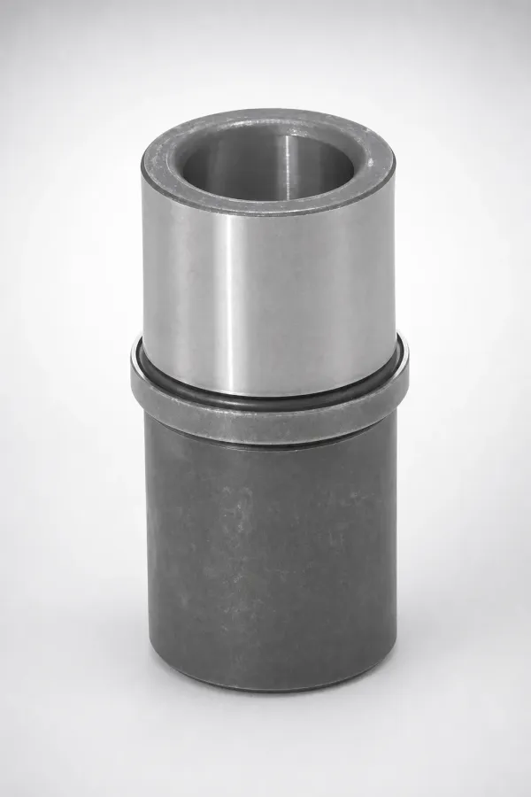
Straight Leader Pin — JIS Standard
SUJ2 | HRC 58-62 | g6 tolerance
View DetailsStraight Leader Pin — DIN Standard
SUJ2 | HRC 58-62 | g6 tolerance
View DetailsStraight Leader Pin — Inch Size
SUJ2 | HRC 58-62 | g6 tolerance
View DetailsStraight Leader Pin — Extra Long
SUJ2 | HRC 58-62 | g6 tolerance
View DetailsStraight Leader Pin — Hardened & Ground
SUJ2 | HRC 58-62 | g6 tolerance
View DetailsStraight Leader Pin — Nitrided
SUJ2 | HRC 58-62 | g6 tolerance
View DetailsJIS vs DIN Leader Pin Standards
Both JIS and DIN standards produce equivalent alignment precision. The choice depends on your mold base standard and regional supply chain.
| Feature | JIS B 5140 | DIN 9825 |
|---|---|---|
| Diameter Range | Ø8 – 60 mm (metric) | Ø10 – 63 mm (metric) |
| Shaft Tolerance | g6 | g6 |
| Head Style | Flanged or plain | Flanged with chamfer |
| Material | SUJ2 (≈ AISI 52100) | 100Cr6 (≡ SUJ2) |
| Mold Base Compatibility | Misumi, Futaba, PUNCH | HASCO, Meusburger, DME Europe |
Deep dive: For a detailed comparison, read JIS vs DIN Leader Pins — What Are the Key Differences?.
About Straight Leader Pins
Straight leader pins are precision-hardened cylindrical shafts that slide into matching leader bushings to align the mold halves during every open-close cycle. Manufactured from SUJ2 bearing steel (equivalent to AISI 52100 / 100Cr6), they achieve HRC 58-62 hardness and g6 shaft tolerance for consistent alignment within ±0.017 mm. Available in JIS B 5140 and DIN 9825 standard dimensions.
Application Scenarios
Standard Two-Plate Molds
Standard injection molds with simple open-close action need reliable, cost-effective alignment between core and cavity halves.
Why it fits: Straight leader pins provide g6 precision with the simplest installation — press-fit into the B-side plate with no secondary machining.
High-Volume Production Molds
Production molds running 1M+ cycles need alignment components that maintain precision without frequent replacement.
Why it fits: SUJ2 bearing steel at HRC 58-62 provides 2M+ cycle life. Centerless-ground g6 finish minimizes bushing wear.
Multi-Cavity Packaging Molds
Multi-cavity molds for caps, closures, and containers need consistent alignment across all cavities to maintain part uniformity.
Why it fits: Straight leader pins ensure identical cavity-to-core alignment in every cavity position, preventing flash and wall thickness variation.
Frequently Asked Questions
What is the standard tolerance for straight leader pins (JIS vs DIN)?+
What diameter range is available for straight leader pins?+
How do I install straight leader pins — press-fit or bolt-fixing?+
Engineering Resources
JIS vs DIN Leader Pins — What Are the Key Differences?
Standard-by-standard comparison of dimensions, tolerances, head styles, and mold base compatibility.
How to Select the Right Straight Leader Pin Diameter for Your Mold
Engineering guide for matching leader pin diameter to mold plate thickness and clamping tonnage.
Need Custom Straight Leader Pins?
Precision straight leader pins manufactured to JIS and DIN standards. Custom dimensions available. MOQ 1 piece.