Guiding Assist Pins
Secondary guide pins positioned at the outer edges of large mold plates to supplement main leader pins and reduce deflection-induced misalignment.
Guiding Assist Pins Products
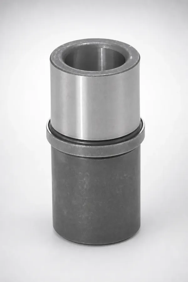
Guiding Assist Pin — Standard
SUJ2 or S45C | HRC 45-62 | Ø12-25 mm
View DetailsGuiding Assist Pin — Long Series
SUJ2 or S45C | HRC 45-62 | Ø12-25 mm
View DetailsGuiding Assist Pin — Hardened
SUJ2 or S45C | HRC 45-62 | Ø12-25 mm
View DetailsGuiding Assist Pin — With Bushing Set
SUJ2 or S45C | HRC 45-62 | Ø12-25 mm
View DetailsWhat Are Guiding Assist Pins and How Do They Work?
In large molds (plate width > 500 mm), the main leader pins at the center or near-center positions cannot prevent edge deflection. During mold close under high clamping tonnage, the plate edges can bow inward by 0.02–0.05 mm — enough to cause flash and parting line mismatch at cavity positions near the edges.
Guiding assist pins are smaller-diameter guide pins (typically Ø12–25 mm) positioned at the four outer corners of the mold plate. They provide supplemental alignment at the plate periphery, reducing edge misalignment to < 0.01 mm even under full clamping load.
Key design rule: guiding assist pin diameter should be 50–70% of the main leader pin diameter. Too small provides insufficient stiffness; too large creates unnecessary machining cost.
About Guiding Assist Pins
Guiding assist pins are secondary alignment pins positioned at the outer corners of large mold plates. They supplement the main leader pins by providing peripheral alignment support, reducing edge deflection under clamping load. Particularly important for molds larger than 500 × 500 mm where main leader pins alone cannot prevent parting line mismatch at edge cavities.
Application Scenarios
Large Automotive Molds
Automotive molds with 800+ mm plate widths experience 0.03-0.05 mm edge deflection under 500+ ton clamping, causing flash at edge cavities.
Why it fits: Guiding assist pins at the four corners reduce edge misalignment from 0.05 mm to < 0.01 mm, eliminating flash without increasing clamping tonnage.
Multi-Cavity Precision Molds
High-cavity molds (32+) with tight dimensional tolerances need consistent alignment across all cavity positions, including edge cavities.
Why it fits: Main leaders align the center; assist pins ensure edge cavities receive the same alignment precision as center cavities.
Frequently Asked Questions
What is a guiding assist pin and how does it differ from a main leader pin?+
Where should guiding assist pins be positioned on the mold?+
What diameter ratio between main leader and assist pin is recommended?+
Engineering Resources
Need Custom Guiding Assist Pins?
Precision guiding assist pins manufactured to JIS and DIN standards. Custom dimensions available. MOQ 1 piece.