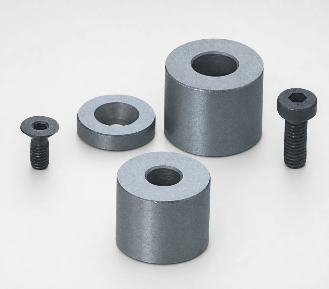
Spacers for Positioning Tapered Pin Set - Countersink, Counterbore Options
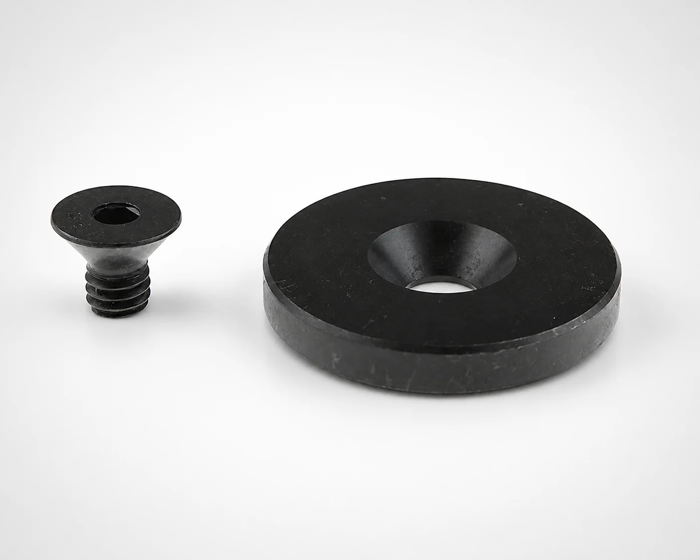
Spacers for Positioning Tapered Pin Set provide controlled spacing for tapered pin alignment, with countersink, counterbore, or through-hole options to match fixture and assembly requirements.
- Spacer component designed to support repeatable tapered pin positioning in assemblies
- Hole geometry options: countersink, counterbore, or through hole for versatile fitting
- Configurable thickness range to suit stacked requirements without redesigning the pin set
- Typical use in machining fixtures, locating assemblies, and precision alignment tooling
Specifications
91 configurations available
| Mounting Hole Shape | D1 (Outer diameter) (mm) | T (Thickness) (mm) | type |
|---|---|---|---|
| Counterbore | 13 | 10 | - |
| Counterbore | 13 | 15 | - |
| Counterbore | 13 | 20 | - |
| Counterbore | 13 | 25 | - |
| Counterbore | 16 | 10 | - |
| Counterbore | 16 | 15 | - |
| Counterbore | 16 | 20 | - |
| Counterbore | 16 | 25 | - |
| Counterbore | 20 | 10 | - |
| Counterbore | 20 | 15 | - |
| Counterbore | 20 | 20 | - |
| Counterbore | 20 | 25 | - |
| Counterbore | 20 | 30 | - |
| Counterbore | 20 | 35 | - |
| Counterbore | 25 | 10 | - |
| Counterbore | 25 | 15 | - |
| Counterbore | 25 | 20 | - |
| Counterbore | 25 | 25 | - |
| Counterbore | 25 | 30 | - |
| Counterbore | 25 | 40 | - |
| Counterbore | 25 | 50 | - |
| Counterbore | 32 | 15 | - |
| Counterbore | 32 | 20 | - |
| Counterbore | 32 | 25 | - |
| Counterbore | 32 | 35 | - |
| Counterbore | 32 | 45 | - |
| Counterbore | 32 | 55 | - |
| Counterbore | 35 | 20 | - |
| Counterbore | 35 | 30 | - |
| Counterbore | 35 | 40 | - |
| Counterbore | 35 | 50 | - |
| Counterbore | 38 | 20 | - |
| Counterbore | 38 | 30 | - |
| Counterbore | 42 | 15 | - |
| Counterbore | 42 | 25 | - |
| Counterbore | 48 | 20 | - |
| Counterbore | 48 | 30 | - |
| Through hole | 8 | 5 | - |
| Through hole | 8 | 10 | - |
| Through hole | 10 | 5 | - |
| Through hole | 10 | 10 | - |
| Through hole | 13 | 5 | - |
| Through hole | 13 | 10 | - |
| Through hole | 16 | 5 | - |
| Through hole | 16 | 10 | - |
| Through hole | 16 | 15 | - |
| Through hole | 16 | 20 | - |
| Through hole | 16 | 25 | - |
| Through hole | 16 | 30 | - |
| Through hole | 16 | 35 | - |
Product Guide
Application Scenarios+
These spacers are used in injection mold tooling and sub-assemblies to maintain repeatable hole spacing for tapered pin alignment. By selecting a matching hole geometry—countersink, counterbore, or through hole—engineers can control how the tapered pin seats relative to the spacer and the mating plate, improving registration during setup and reassembly.
- Leader/ejector positioning in automotive connector molds: In multi-cavity housings and slide-related components, stable alignment reduces wear and misfit as parts cycle and are serviced.
- Medical device housings requiring tight assembly repeatability: Spacer-controlled alignment helps maintain consistent cavity/core orientation through tooling maintenance, where fixtures must be re-mounted without re-machining.
- Precision alignment tooling and machining fixtures: The ability to choose thickness for stacked requirements enables controlled datum spacing while keeping the tapered pin set geometry consistent.
The variant is suited because it supports controlled spacing for tapered pin sets and offers practical hole-shape options to suit different mating hardware and fixture stack designs.
Material & Process Details+
The provided data does not specify the steel grade, hardness (HRC), heat treatment condition, or coatings for this spacer family. As a result, material-specific performance statements (e.g., wear resistance vs. toughness trade-offs, nitriding vs. quench & temper) cannot be validated from the current specification.
For accurate selection in mold environments, request or confirm the spacer material/heat-treatment specification from the supplier before finalizing the design. In general, alignment components typically require good dimensional stability and resistance to fretting/impact during repeated assembly; these properties are strongly influenced by the exact steel grade and processing route.
- Key missing parameters: steel grade designation, target hardness in HRC, heat treatment state (e.g., pre-hardened, quenched & tempered), and any surface treatment.
- Recommendation: verify compatibility with the mating tapered pin material and the expected loads (assembly force, alignment precision requirements, and maintenance frequency).
Sizing & Selection Guide+
Use the spacer dimensions to match the cavity/core spacing datum established by your tapered pin set. Two variable dimensions are provided: D1 (outer diameter) = 8 ~ 48 mm and T (thickness) = 5 ~ 55 mm.
- Step 1: Select hole geometry: choose counterbore, through hole, or countersink based on how the tapered pin should seat in the mating components.
- Step 2: Match D1 (outer diameter): ensure D1 provides sufficient clearance and bearing area for the surrounding plate/features. Pick a value within 8–48 mm to fit the available pocket or surrounding structure.
- Step 3: Set stacking thickness T: choose 5–55 mm so the spacer stack achieves the required axial spacing for alignment. Use the thickness to avoid redesign when building up multiple components.
Tolerances are not specified in the provided data; confirm the intended fit class (clearance vs. close tolerance) with your tapered pin interface drawings to maintain alignment repeatability.
Frequently Asked Questions
How do I choose between countersink, counterbore, and through-hole variants for a tapered pin alignment stack?+
What D1 and thickness ranges are available for this spacer series?+
Can this spacer be used to adjust stack height without redesigning the tapered pin set?+
What steel grade and hardness are used for these spacers, and what heat treatment is applied?+
What dimensional tolerances apply between the spacer and tapered pin interface?+
Related Products
Need Custom Specifications?
Our engineering team can help with custom configurations, material selection, and volume pricing.