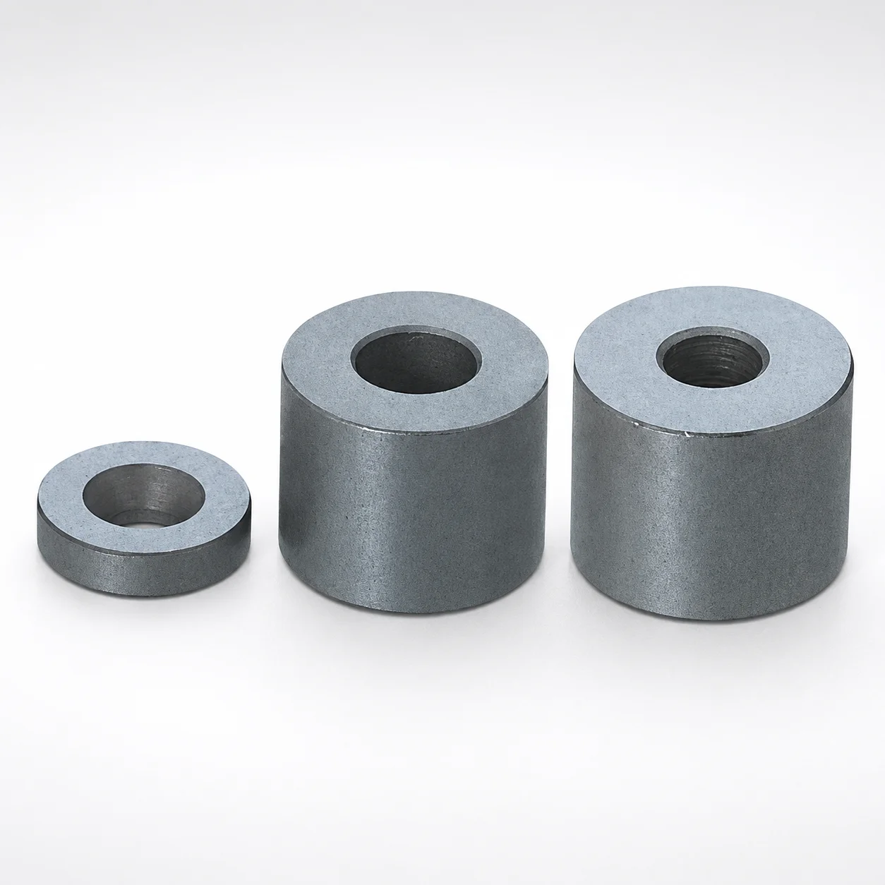
Spacers for Positioning Tapered Pin Set
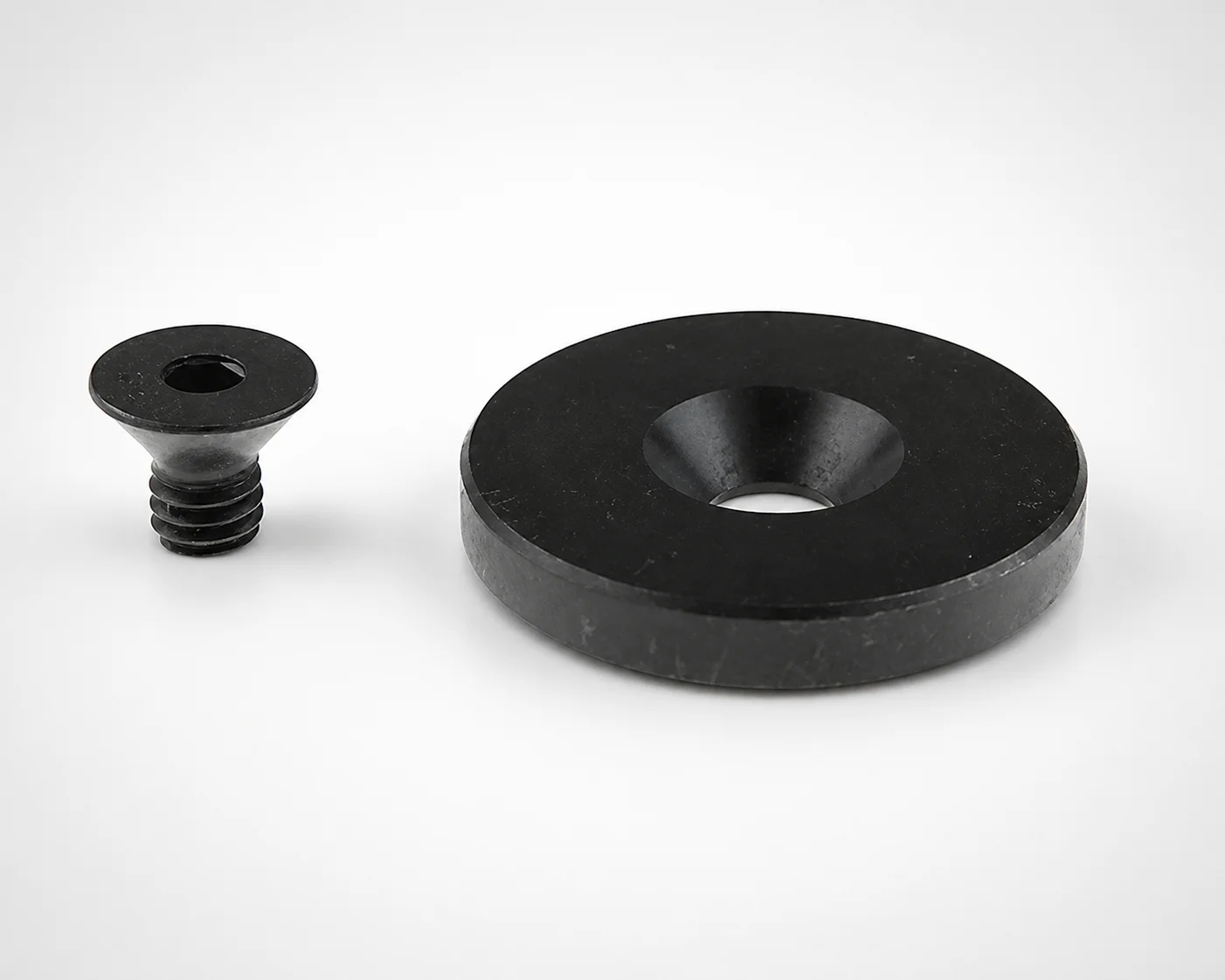
Spacers for Positioning Tapered Pin Set are designed to set accurate spacing and alignment for tapered pin assemblies. Configure hole style to match your fastening layout and improve assembly consistency.
- Spacer component with pin-oriented shape for controlled positioning
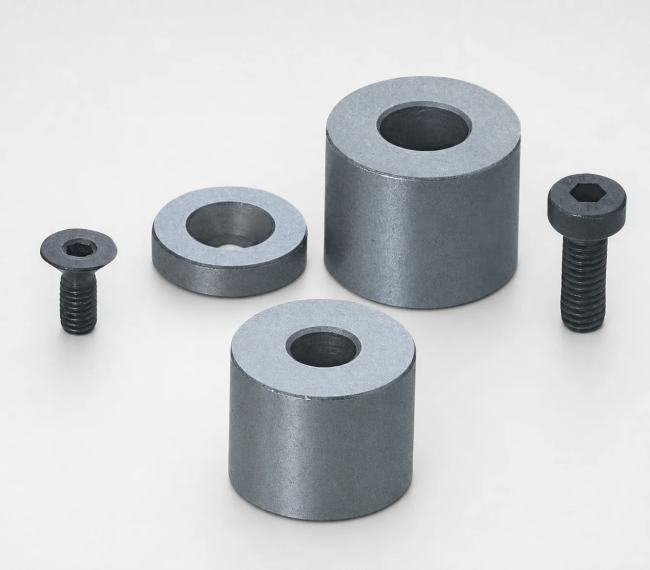
- Selectable mounting hole styles: counterbore, countersink, or through hole
- Flexible thickness design supports fit-up across different stack heights
- Used in fixtures, jig assemblies, and precision locating applications
Specifications
22 configurations available
| Mounting Hole Shape | D1 (Outer diameter) (mm) | T (Height) (mm) | type |
|---|---|---|---|
| Counterbore | 13 | 10 ~ 25 | - |
| Counterbore | 16 | 10 ~ 25 | - |
| Counterbore | 20 | 10 ~ 35 | - |
| Counterbore | 25 | 10 ~ 50 | - |
| Counterbore | 32 | 15 ~ 55 | - |
| Counterbore | 35 | 20 ~ 50 | - |
| Counterbore | 38 | 20 ~ 50 | - |
| Counterbore | 42 | 15 ~ 45 | - |
| Counterbore | 48 | 20 ~ 40 | - |
| Through hole | 8 | 1 ~ 10 | - |
| Through hole | 10 | 1 ~ 10 | - |
| Through hole | 13 | 1 ~ 10 | - |
| Through hole | 16 | 1 ~ 35 | - |
| Through hole | 20 | 1 ~ 50 | - |
| Through hole | 25 | 1 ~ 55 | - |
| Through hole | 30 | 1 ~ 50 | - |
| Through hole | 35 | 1 ~ 45 | - |
| Through hole | 42 | 1 ~ 40 | - |
| Countersink | 16 | 5 ~ 10 | - |
| Countersink | 20 | 5 ~ 10 | - |
| Countersink | 25 | 6 ~ 10 | - |
| Countersink | 32 | 6.5 ~ 10 | - |
Product Guide
Application Scenarios+
These spacers are used inside injection mold tooling to control the separation and repeatable alignment of tapered pin assemblies in leader/ejector space components. By matching the spacer to the fastening layout, you can reduce stack-up variation and keep locating accuracy stable over repeated cycles.
- Automotive connector and housing molds: Install the spacer between base components and tapered pin interfaces to maintain consistent ejector travel alignment and improve assembly consistency under high duty operation. The available hole styles (counterbore, countersink, through) help match different screw and pin capture geometries.
- Medical device housings: Use the selectable thickness range to fine-tune fixture stack heights for precision alignment of small locating features, supporting stable part-to-part repeatability.
- Precision jig/fixture subassemblies: Employ the controlled positioning geometry to ensure tight tolerance fit-up while allowing straightforward reconfiguration of hole type to suit different mounting requirements.
Material & Process Details+
The provided product data specifies spacer geometry and mounting hole options but does not include a steel grade, heat treatment state, or hardness (HRC). As a result, the specific material properties, wear resistance, and toughness trade-offs for this variant cannot be stated from the available specifications.
- Material/heat treatment: Not specified in the input data (e.g., no SKD61/H13, nitrided, or quenched & tempered condition given).
- Hardness and performance: Hardness (HRC) and expected wear behavior are not provided, so selections should be confirmed in the technical documentation for the actual part supply.
- Manufacturing process: Not specified (e.g., machining, surface treatment, or finishing steps are not listed).
If you share the supplier’s material certificate or an alternate dataset that includes grade and heat treatment, I can update this section with precise equivalents and target hardness.
Sizing & Selection Guide+
Select dimensions based on the spacer’s mounting hole style and its physical stack height to match the tapered pin interface in your mold assembly.
- Choose mounting hole shape: Use counterbore, countersink, or through hole to align with your screw head clearance and fastening layout.
- Match outer diameter (D1): Confirm your required spacer outer diameter falls within D1 = 8 ~ 48 mm. This should be checked against surrounding clearance in the mold base/plate to avoid interference.
- Match thickness/height (T): Set the required stack separation using T = 1 ~ 20 mm. Use the thickness that achieves the intended gap and alignment for the tapered pin assembly.
- Tolerance/fit: Because the dataset does not provide tolerances, validate fit in CAD using the actual drawing tolerance values from the part specification sheet, especially where the spacer interfaces with the pin seats or fasteners.
For mixed builds, treat hole style as configurable per your fastening design, while D1 and T must be selected from the stated ranges.
Frequently Asked Questions
How do I choose between counterbore, countersink, and through-hole mounting for tapered pin spacer stacks?+
What outer diameter (D1) and height (T) options are available for this spacer, and how do they affect stack-up alignment?+
Can this spacer be used to fine-tune alignment between mold components in leader/ejector space applications?+
Are the spacer material grade and heat treatment specified for wear resistance and toughness performance?+
What should I verify regarding tolerances when integrating the spacer into a precision locating stack?+
Related Products
Need Custom Specifications?
Our engineering team can help with custom configurations, material selection, and volume pricing.