Two Step Ejector Pins
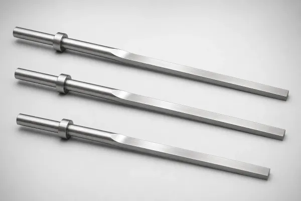
Dual diameter transitions (head �?middle �?shaft) for complex multi-level cavities with two stacked bore diameters. 1 product series.
Products (1 Series)
One-Step vs Two-Step: When Do You Need Two Steps?
| Condition | Use One-Step | Use Two-Step |
|---|---|---|
| Internal feature | Single counterbore | Two stacked counterbores at different diameters |
| Diameter transitions | 1 transition sufficient | 2 transitions required to match cavity |
| Alternative | Standard choice | Consider 2× one-step pins if geometry allows separate ejection points |
Decision rule: Use two-step only when the part has two distinct bore diameters stacked vertically and a single ejection point is required. If separate ejection points work, two one-step pins are easier to source and replace.
Do You Need a Two-Step Ejector Pin?
Two-step pins are a specialty product. Confirm your part geometry requires three diameter sections:
✅ Two-step is the right choice if:
- The molded part has a three-diameter internal feature (e.g., stepped bore with intermediate shoulder)
- The ejection stroke passes through two plate transitions at different diameters
- A single pin must eject a feature with three distinct cross-sections
- The part design cannot be modified to eliminate the third diameter
🔄 Use one-step instead if:
- The part has only two diameters → One-Step Ejector Pins (17 series, more options)
- You can use two separate one-step pins at different heights → simpler, cheaper maintenance
- The intermediate diameter is cosmetic only → a one-step pin with slightly larger shaft may work
- Budget is constrained → two-step pins are 2-3× more expensive per unit than one-step
Decision rule: Two-step pins are justified only when the part geometry physically requires three concentric diameters in the ejection path. If in doubt, try a one-step pin first — it covers 95% of stepped ejection applications. See our When to Use Two-Step vs Two Separate One-Step Ejector Pins.
About
Two-step ejector pins have three diameter sections connected by two transitions. They address complex cavity geometries where a single one-step pin cannot match the full cavity profile. The middle section acts as a precision guide between the two bore diameters.
Application Scenarios
Multi-Level Sensor Housings
Sensor housings with two concentric bores for sensing element and wiring
Why it fits: Two-step pin matches both bore diameters in a single ejection stroke.
Recommended: M2, h6 tolerance on all three diameters
Frequently Asked Questions
What are the three diameter options for two-step ejector pins?+
When is a two-step pin necessary vs using two separate one-step pins?+
What is the maximum length for two-step ejector pins?+
Engineering Resources
Need a Custom Quote?
Specify your requirements and we'll respond within 1 business day.