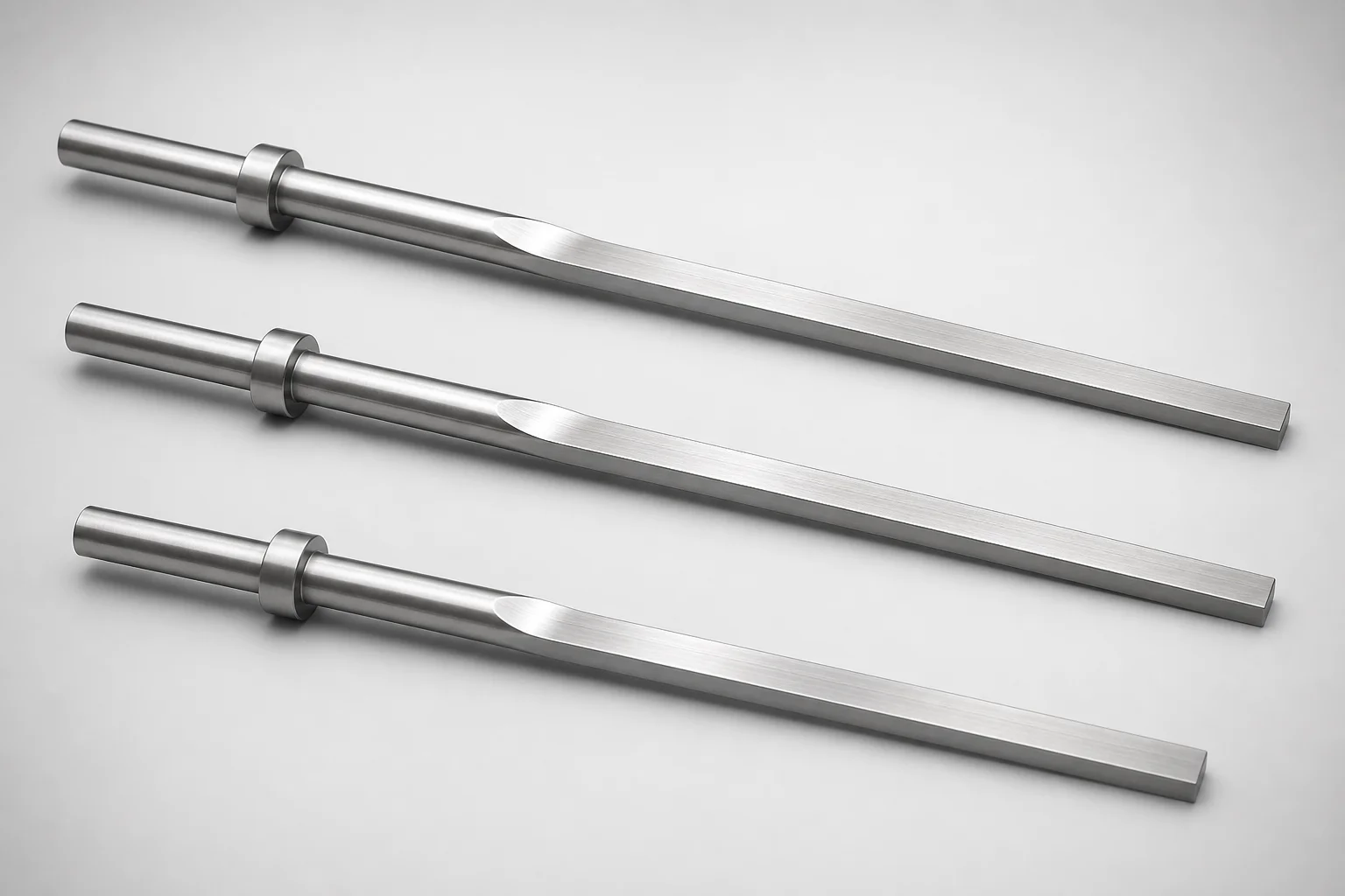
M2 Steel Rectangular Ejector Pins with Free Flange Position
Rectangular ejector pins with free flange position (M2 steel) provide stable, reliable ejection by allowing precise flange positioning in the mold. The rectangular geometry supports predictable removal performance and helps protect mold components during production.
- Free flange-position design for accurate alignment in mold assemblies
- Quenched M2 steel construction for wear-resistant ejection performance
- Supports controlled tip tolerance options (0/−0.005, 0/−0.01)
- Used in injection molding and high-cycle forming applications
Specifications
22 configurations available
| Tip Tolerance Reference | P (Rectangular Type Tip Size) (mm) | W (Rectangular Type Tip Size) (mm) | D (Shank diameter) (mm) | L (P dimension side length) (mm) | Dimension N (mm) | S (D dimension length) (mm) | type |
|---|---|---|---|---|---|---|---|
| 0/-0.005 | 0.3 ~ 0.8 | 0.3 ~ 0.8 | 1 | 50 ~ 100 | 23 ~ 70 | 5 ~ 40 | - |
| 0/-0.005 | 0.6 ~ 1.3 | 0.3 ~ 1.3 | 1.5 | 50 ~ 100 | 23 ~ 70 | 5 ~ 40 | - |
| 0/-0.005 | 0.8 ~ 1.8 | 0.3 ~ 1.8 | 2 | 50 ~ 200 | 23 ~ 170 | 5 ~ 40 | - |
| 0/-0.005 | 0.8 ~ 2.3 | 0.3 ~ 2.3 | 2.5 | 50 ~ 200 | 26 ~ 170 | 5 ~ 40 | - |
| 0/-0.005 | 0.8 ~ 2.8 | 0.3 ~ 2.8 | 3 | 50 ~ 200 | 27 ~ 170 | 5 ~ 50 | - |
| 0/-0.005 | 1 ~ 3.3 | 0.3 ~ 3.3 | 3.5 | 50 ~ 200 | 27 ~ 170 | 5 ~ 50 | - |
| 0/-0.005 | 1 ~ 3.8 | 0.3 ~ 3.8 | 4 | 50 ~ 200 | 29 ~ 170 | 5 ~ 50 | - |
| 0/-0.005 | 1.2 ~ 4.3 | 0.4 ~ 4.3 | 4.5 | 50 ~ 200 | 29 ~ 170 | 5 ~ 50 | - |
| 0/-0.005 | 1.5 ~ 4.8 | 0.4 ~ 4.8 | 5 | 50 ~ 200 | 31 ~ 170 | 5 ~ 50 | - |
| 0/-0.005 | 1.8 ~ 5.3 | 0.5 ~ 5.3 | 5.5 | 50 ~ 200 | 31 ~ 170 | 5 ~ 50 | - |
| 0/-0.005 | 2 ~ 5.8 | 0.5 ~ 5.8 | 6 | 50 ~ 200 | 33 ~ 170 | 5 ~ 50 | - |
| 0/-0.01 | 0.3 ~ 0.8 | 0.3 ~ 0.8 | 1 | 50 ~ 100 | 23 ~ 50 | 5 ~ 40 | - |
| 0/-0.01 | 0.6 ~ 1.3 | 0.3 ~ 1.3 | 1.5 | 50 ~ 100 | 23 ~ 50 | 5 ~ 40 | - |
| 0/-0.01 | 0.8 ~ 1.8 | 0.3 ~ 1.8 | 2 | 50 ~ 200 | 23 ~ 170 | 5 ~ 40 | - |
| 0/-0.01 | 0.8 ~ 2.3 | 0.3 ~ 2.3 | 2.5 | 50 ~ 200 | 26 ~ 170 | 5 ~ 40 | - |
| 0/-0.01 | 0.8 ~ 2.8 | 0.3 ~ 2.8 | 3 | 50 ~ 200 | 27 ~ 170 | 5 ~ 50 | - |
| 0/-0.01 | 1 ~ 3.3 | 0.3 ~ 3.3 | 3.5 | 50 ~ 200 | 27 ~ 170 | 5 ~ 50 | - |
| 0/-0.01 | 1 ~ 3.8 | 0.3 ~ 3.8 | 4 | 50 ~ 200 | 29 ~ 170 | 5 ~ 50 | - |
| 0/-0.01 | 1.2 ~ 4.3 | 0.4 ~ 4.3 | 4.5 | 50 ~ 200 | 29 ~ 170 | 5 ~ 50 | - |
| 0/-0.01 | 1.5 ~ 4.8 | 0.4 ~ 4.8 | 5 | 50 ~ 200 | 31 ~ 170 | 5 ~ 50 | - |
| 0/-0.01 | 1.8 ~ 5.3 | 0.5 ~ 5.3 | 5.5 | 50 ~ 200 | 31 ~ 170 | 5 ~ 50 | - |
| 0/-0.01 | 2 ~ 5.8 | 0.5 ~ 5.8 | 6 | 50 ~ 200 | 33 ~ 170 | 5 ~ 50 | - |
Product Guide
Application Scenarios+
Rectangular ejector pins with a free flange position are used in injection mold tooling where part release must stay consistent over long production runs. The free-flange layout helps the pin align during assembly, supporting stable contact and controlled movement at the ejecting stage.
- Automotive and appliance components: In high-cycle molds for small housings, brackets, or inserts, the rectangular tip geometry (P 0.3–2 mm, W 0.3–0.5 mm) improves predictable removal and reduces the risk of uneven edge loading.
- Air-jet valve and accessory tooling: For ejector systems integrated with air-jet or auxiliary release functions, the free flange position supports accurate setup and smooth ejection timing, reducing localized wear at the contact area.
- General precision ejection: When controlled tip tolerance is required (0/−0.005 or 0/−0.01), this variant is suited for molds needing repeatable clearance and reduced flash or scuffing on molded surfaces.
Overall, the M2 construction and alignment-oriented flange positioning are well suited to durable, reliable ejecting in demanding mold setups.
Material & Process Details+
This ejector pin uses M2 steel in a quenched condition, emphasizing wear resistance for ejection features that experience repeated contact and sliding. M2 (high-speed steel family) is selected when longer service life is required in high-cycle molds and when tip surfaces must resist abrasion.
- Heat treatment state: Supplied as quenched M2 steel, targeting a hard, wear-focused microstructure.
- Hardness & performance trade-off: Quenched M2 typically provides high hardness for edge retention, improving abrasion resistance; however, increased hardness can reduce toughness compared with softer tool steels, so proper alignment and controlled tip tolerance are important to avoid chipping.
- Manufacturing relevance: Rectangular tip and free-flange features are typically produced from bar/blank stock and then machined and finished to maintain the specified tip tolerances (0/−0.005 or 0/−0.01).
If compared with general-purpose tool steels, M2 generally prioritizes wear resistance for ejection wear points, while requiring careful setup to manage toughness under intermittent shock loads.
Sizing & Selection Guide+
Select the ejector pin dimensions by matching the working tip geometry and the installed travel interface to your mold cavity/core design. Start with the tip size: choose P (rectangular type tip size) from 0.3 to 2 mm and W from 0.3 to 0.5 mm to align with the part-release contact area.
- Pin shank diameter (D): pick a shank diameter from 1 to 6 mm based on the guide hole size and desired stiffness to prevent deflection during ejection.
- Length (L): verify L against your mold stack and required ejector stroke envelope. Available L ranges include 50–100 and 50–200 (depending on configuration).
- Flange/interface dimensions: set N within 23–33 mm and S within 5–40 or 5–50 mm to ensure correct positioning of the free flange in the mold assembly.
- Tolerance & fit: select the tip tolerance option—0/−0.005 or 0/−0.01—to control clearance, reduce scuffing, and maintain consistent ejection gap.
Use the rectangular tip size and the D/L envelope first, then validate N/S to ensure the free flange position settles correctly during assembly.
Frequently Asked Questions
How do I choose between the tip tolerance options 0/−0.005 and 0/−0.01 for this free-flange ejector pin?+
The available tip tolerances are 0/−0.005 and 0/−0.01. Choose 0/−0.005 when you need tighter control of the effective tip size for consistent clearance and reduced surface marking. Select 0/−0.01 if your mold design can accommodate a slightly larger functional clearance while still meeting ejection reliability requirements.
What tip geometry ranges are available for the rectangular type (P and W) on this ejector pin?+
The rectangular tip dimensions are specified as P = 0.3–2 mm and W = 0.3–0.5 mm. These ranges help you size the contact area to the part-release surface without overextending the pin into sensitive features. Use these values first, then confirm D and L fit the guide and mold stack.
How should I verify shank diameter and length compatibility with my ejector guide and mold stack?+
Confirm the shank diameter D = 1–6 mm matches your guide hole and desired stiffness. Then check the available pin lengths L = 50–100 or 50–200 against the required installed length and ejector travel envelope. Validate N and S as well, since the free flange positioning depends on these interface dimensions.
What do the N and S dimension ranges control in the mold assembly for free flange positioning?+
N is given as 23–33 mm, and S as 5–40 or 5–50 mm. These dimensions relate to the flange and interface layout that sets the free flange position during assembly. Matching N/S to your mold’s component stackup helps ensure proper seating, reducing misalignment and uneven ejection wear.
Why is M2 steel quenched construction used for ejection parts, and what is the practical implication for wear and toughness?+
This product is built from quenched M2 steel to prioritize wear resistance at the ejecting tip. Higher hardness typically improves abrasion resistance, supporting long service life in high-cycle setups. However, very hard states can lower toughness versus softer steels, so maintaining correct alignment and selecting the appropriate tip tolerance helps avoid chipping or edge damage under load.
Need Custom Specifications?
Our engineering team can help with custom configurations, material selection, and volume pricing.