Straight Free Flange-Position Ejector Pins
Round cross-section ejector pins with adjustable flange position for non-standard plate thicknesses. 3 product series.
Products (3 Series)
About
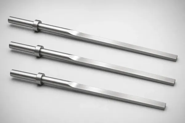
Straight free flange-position ejector pins combine the simplicity of a round cross-section with the flexibility of an adjustable head position. The flange can be set anywhere along the shaft to match non-standard ejector retainer plate thicknesses. Secured by set screw after positioning. Shaft tolerance h6 standard.
Application Scenarios
Legacy Mold Repair
Molds with unknown or non-standard plate specifications.
Why it fits: Measure actual plate stack-up and set flange position to match.
Recommended: M2, h6, adjustable flange
Frequently Asked Questions
What is the flange position adjustment range?+
The flange (head) can be positioned anywhere along the shaft length, with a typical adjustment range from 10mm below the plate surface to 50mm above. The exact range depends on the shaft length — for a 200mm shaft, the flange can be set at any point from 10mm to 190mm from the tip. This flexibility eliminates the need for custom-length pins when the ejection stroke requires non-standard pin positioning relative to the ejector plate. The flange is secured by a set screw or collet mechanism (depending on the series) and can be repositioned during mold setup without removing the pin from the plate.
What shaft diameters are available for straight free-flange pins?+
Standard catalog shaft diameters range from ø1.0mm to ø16mm for M2 steel (SKH51) and ø2.0mm to ø12mm for H13 nitrided (SKD61). The flange outer diameter is typically 1.5× to 2× the shaft diameter, matching standard ejector plate counterbore dimensions. Configurable-length series allow shaft lengths from 50mm to 300mm in 0.5mm increments. For special diameters outside the catalog range, custom production is available with a 5–7 day lead time and MOQ of 10 pieces.
How is the flange secured after positioning?+
Two securing mechanisms are used depending on the series: (1) Set screw type — a radial set screw in the flange body locks against the shaft surface. This allows infinite positioning along the shaft but may leave a small indentation on the shaft surface. (2) Collet clamp type — a split collet in the flange bore grips the shaft when tightened. This provides higher clamping force without marking the shaft, allowing the pin to be repositioned repeatedly. Both mechanisms maintain position under ejection forces up to 500N. For high-force applications (above 500N), the set screw type is recommended because the collet may slip under extreme loads.
Engineering Resources
Need a Custom Quote?
Specify your requirements �?we respond within 1 business day.
�?MOQ 1 piece�?Same-day shipping