Ejector Blades �?With Tip Processing
Pre-machined tip profiles on rectangular ejector blades �?angle cuts, chamfers, and compound surfaces to match contoured part surfaces. 3 product series.
Products (3 Series)
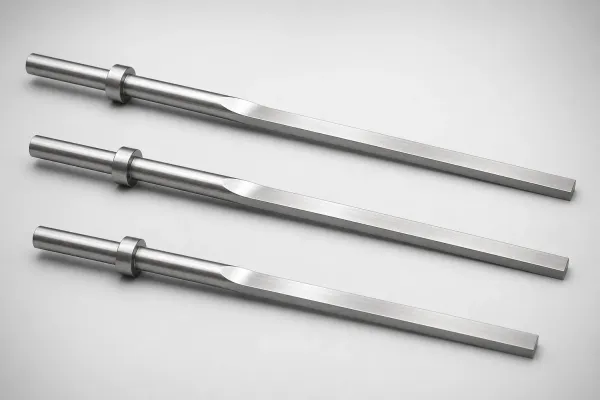
Tip Processing Options for Ejector Blades
Three standard tip profiles match different rib geometries and draft angles:
| Tip Type | Machining | Best For | Tolerance |
|---|---|---|---|
| Flat Grind | 0.03–0.05mm removed from tip face | Flush ejection surface, eliminating recess marks | ±0.02mm |
| Angle Cut | 5°–15° ground angle matching rib draft | Ribs with draft angle, preventing drag marks | ±0.02mm |
| Step Cut | 0.1–0.3mm step into tip face | Parts with raised features inside ribs | ±0.03mm |
| Compound Angle | Two-plane CNC machining (special order) | Ribs with longitudinal + transverse taper | ±0.02mm |
Selection tip: Flat grind is the default — it covers 70% of blade tip applications. Switch to angle cut only when the rib has a visible draft angle that would cause drag marks with a flat tip. For compound angle specifications and ordering, see our Blade Tip Processing: Angle Cuts for Part Feature Matching.
About
Tip-processed ejector blades have the ejection face machined to match the contour of the molded part surface. This prevents drag marks during ejection on angled or curved rib surfaces. Standard tip options include single-angle cuts (5° to 45°), chamfers, and compound angles requiring multi-axis CNC.
Application Scenarios
Angled Rib Ejection
Reinforcement ribs with drafted side walls where the rib bottom is not perpendicular to the ejection direction.
Why it fits: Angle-cut blade tip matches the rib bottom contour, ensuring full-area contact during ejection and preventing edge drag marks.
Recommended: Single-angle cut, M2, angle matched to rib draft
Frequently Asked Questions
What tip processing options are available for ejector blades?+
Can compound angles be machined on blade tips?+
What is the tolerance on tip-processed blade surfaces?+
Engineering Resources
Need a Custom Quote?
Specify your requirements �?we respond within 1 business day.