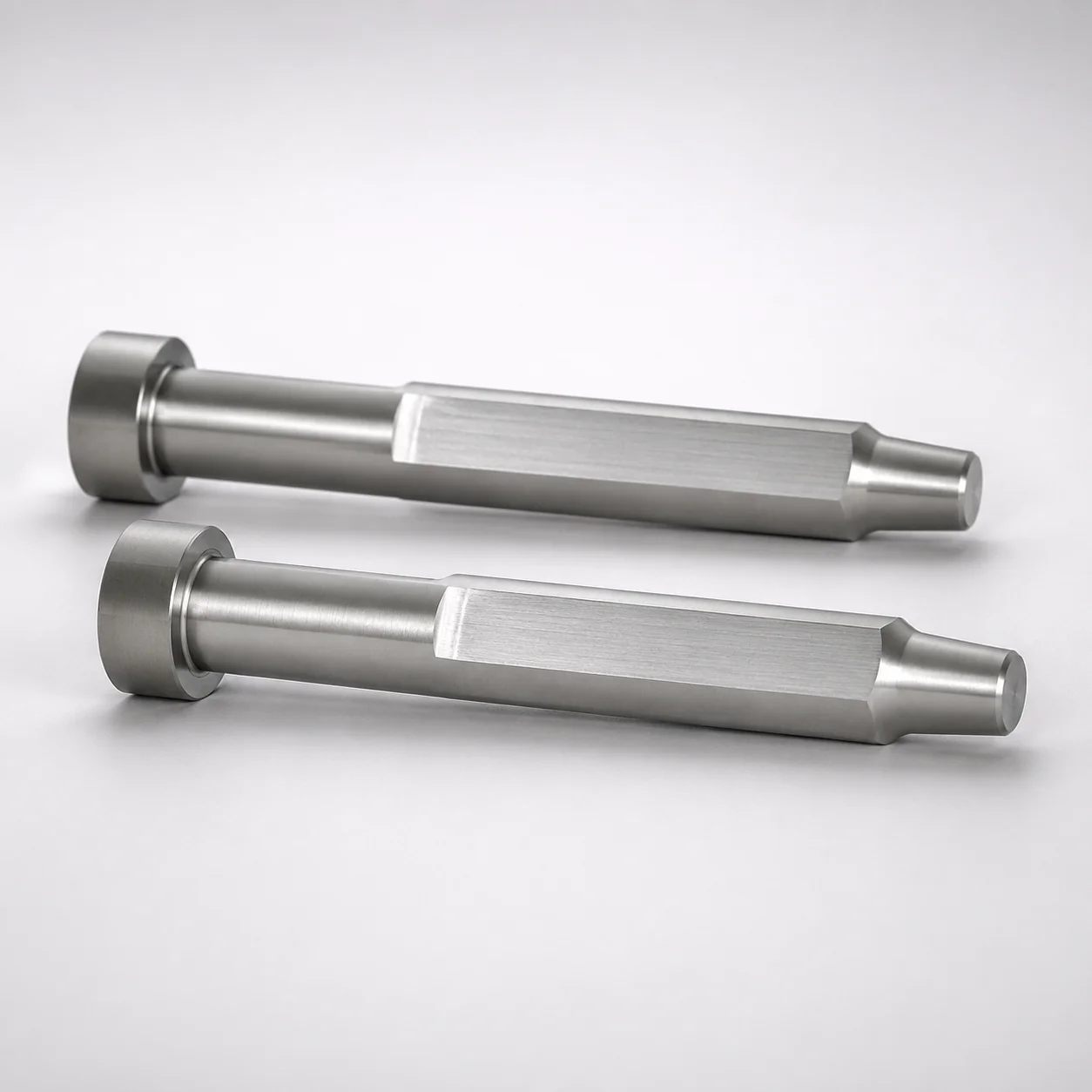
JIS Standard SKH51 Steel Gas Release One-Step Core Pins Flat Sides
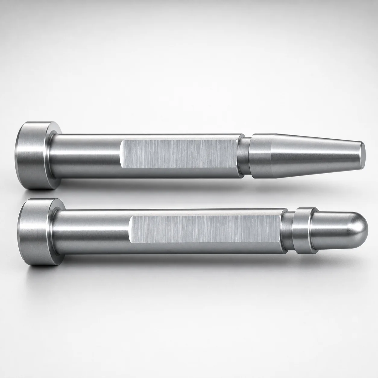
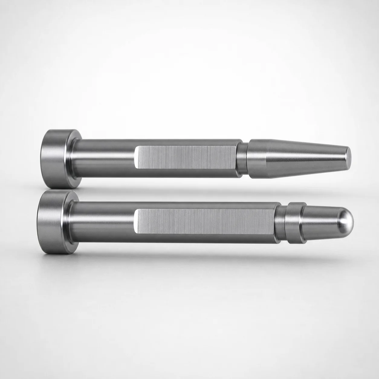
Gas Release One-Step Core Pins (SKH51 steel) with flat sides are designed for stable locating in the core set while improving mold gas venting during production. The one-step geometry simplifies installation and maintains reliable ejection alignment.
- One-step gas-release shape with no second step for consistent core positioning
- SKH51 steel construction with quenched hardening for wear resistance in repeated cycles
- L dimension tolerance options support tight assembly requirements for mold build-up
- Common for injection tooling applications requiring controlled exhaust and repeatable ejection
Specifications
6438 configurations available
| Shaft Diameter Tolerance | L Dimension Tolerance | Tip Gradient Tolerance | D/P (Shaft Diameter) (mm) | First Step Shape | Tip Shape | No. (Nominal diameter) (mm) | Cutting facets (facet) | A (Step shape diameter) (mm) | C (Step type taper width) (mm) | CVC (Designation of C dimension in increments of 0.01mm) (mm) | E (Facet cutting depth) (mm) | F (Bearing bore length) (mm) | G (Tip C chamfering width) (mm) | K (Tip angle) (°) | L (L dimension) (mm) | Q (Tip R chamfering) (mm) | S (Tip tapered width) (mm) | V (Tip diameter) (mm) | VC (V dimension alteration, smaller than V min) (mm) | type |
|---|---|---|---|---|---|---|---|---|---|---|---|---|---|---|---|---|---|---|---|---|
| 0/-0.005 | +0.02/0 | ±0.01 | 1 | 1B | No processing | - | 1 faces | 0.4 ~ 0.99 | - | - | 0.02 ~ 0.05 | 25 ~ 99.3 | - | - | 16.5 ~ 100 | - | - | 0.5 ~ 0.99 | - | - |
| 0/-0.005 | +0.02/0 | ±0.01 | 1 | 1B | No processing | - | 1 faces | 0.4 ~ 0.99 | - | - | 0.02 ~ 0.05 | 25 ~ 99.3 | - | - | 16.5 ~ 100 | - | - | - | 0.4 ~ 0.49 | - |
| 0/-0.005 | +0.02/0 | ±0.01 | 1.5 | 1B | No processing | - | 1 faces | 0.4 ~ 1.49 | - | - | 0.02 ~ 0.05 | 25 ~ 99 | - | - | 16.5 ~ 100 | - | - | 0.5 ~ 1.49 | - | - |
| 0/-0.005 | +0.02/0 | ±0.01 | 1.5 | 1B | No processing | - | 1 faces | 0.4 ~ 1.49 | - | - | 0.02 ~ 0.05 | 25 ~ 99 | - | - | 16.5 ~ 100 | - | - | - | 0.4 ~ 0.49 | - |
| 0/-0.005 | +0.02/0 | ±0.01 | 2 | 1B | No processing | - | 1 faces | 0.5 ~ 1.99 | - | - | 0.02 ~ 0.05 | 25 ~ 99 | - | - | 16.5 ~ 100 | - | - | 0.5 ~ 1.99 | - | - |
| 0/-0.005 | +0.02/0 | ±0.01 | 2.5 | 1B | No processing | - | 1 faces | 0.5 ~ 2.49 | - | - | 0.02 ~ 0.05 | 25 ~ 99 | - | - | 16.5 ~ 100 | - | - | 0.5 ~ 2.49 | - | - |
| 0/-0.005 | +0.02/0 | ±0.01 | 3 | 1B | No processing | - | 1 faces | 0.7 ~ 2.99 | - | - | 0.02 ~ 0.05 | 25 ~ 99 | - | - | 16.5 ~ 100 | - | - | 0.7 ~ 2.99 | - | - |
| 0/-0.005 | +0.02/0 | ±0.01 | 3.5 | 1B | No processing | - | 1 faces | 0.7 ~ 3.49 | - | - | 0.02 ~ 0.05 | 25 ~ 119.5 | - | - | 16.5 ~ 120 | - | - | 1 ~ 3.49 | - | - |
| 0/-0.005 | +0.02/0 | ±0.01 | 3.5 | 1B | No processing | - | 1 faces | 0.7 ~ 3.49 | - | - | 0.02 ~ 0.05 | 25 ~ 119.5 | - | - | 16.5 ~ 120 | - | - | - | 0.7 ~ 0.99 | - |
| 0/-0.005 | +0.02/0 | ±0.01 | 4 | 1B | No processing | - | 1 faces | 0.7 ~ 3.99 | - | - | 0.02 ~ 0.05 | 25 ~ 119.5 | - | - | 16.5 ~ 120 | - | - | 1 ~ 3.99 | - | - |
| 0/-0.005 | +0.02/0 | ±0.01 | 4 | 1B | No processing | - | 1 faces | 0.7 ~ 3.99 | - | - | 0.02 ~ 0.05 | 25 ~ 119.5 | - | - | 16.5 ~ 120 | - | - | - | 0.7 ~ 0.99 | - |
| 0/-0.005 | +0.02/0 | ±0.01 | 4.5 | 1B | No processing | - | 1 faces | 1 ~ 4.49 | - | - | 0.02 ~ 0.05 | 25 ~ 119.5 | - | - | 16.5 ~ 120 | - | - | 1 ~ 4.49 | - | - |
| 0/-0.005 | +0.02/0 | ±0.01 | 5 | 1B | No processing | - | 1 faces | 1 ~ 4.99 | - | - | 0.02 ~ 0.05 | 25 ~ 119.5 | - | - | 16.5 ~ 120 | - | - | 1 ~ 4.99 | - | - |
| 0/-0.005 | +0.02/0 | ±0.01 | 5.5 | 1B | No processing | - | 1 faces | 1 ~ 5.49 | - | - | 0.02 ~ 0.05 | 25 ~ 149.3 | - | - | 16.5 ~ 120 | - | - | 1.5 ~ 5.49 | - | - |
| 0/-0.005 | +0.02/0 | ±0.01 | 5.5 | 1B | No processing | - | 1 faces | 1 ~ 5.49 | - | - | 0.02 ~ 0.05 | 25 ~ 149.3 | - | - | 16.5 ~ 120 | - | - | - | 1 ~ 1.49 | - |
| 0/-0.005 | +0.02/0 | ±0.01 | 6 | 1B | No processing | - | 1 faces | 1.5 ~ 5.99 | - | - | 0.02 ~ 0.05 | 25 ~ 119.5 | - | - | 16.5 ~ 120 | - | - | 2 ~ 5.99 | - | - |
| 0/-0.005 | +0.02/0 | ±0.01 | 6 | 1B | No processing | - | 1 faces | 1.5 ~ 5.99 | - | - | 0.02 ~ 0.05 | 25 ~ 119.5 | - | - | 16.5 ~ 120 | - | - | - | 1.5 ~ 1.99 | - |
| 0/-0.005 | +0.02/0 | ±0.01 | 7 | 1B | No processing | - | 1 faces | 1.5 ~ 6.99 | - | - | 0.02 ~ 0.05 | 25 ~ 149.3 | - | - | 16.5 ~ 120 | - | - | 2 ~ 6.99 | - | - |
| 0/-0.005 | +0.02/0 | ±0.01 | 7 | 1B | No processing | - | 1 faces | 1.5 ~ 6.99 | - | - | 0.02 ~ 0.05 | 25 ~ 149.3 | - | - | 16.5 ~ 120 | - | - | - | 1.5 ~ 1.99 | - |
| 0/-0.005 | +0.02/0 | ±0.01 | 8 | 1B | No processing | - | 1 faces | 1.5 ~ 7.99 | - | - | 0.02 ~ 0.05 | 25 ~ 149.3 | - | - | 16.5 ~ 120 | - | - | 2 ~ 7.99 | - | - |
| 0/-0.005 | +0.02/0 | ±0.01 | 8 | 1B | No processing | - | 1 faces | 1.5 ~ 7.99 | - | - | 0.02 ~ 0.05 | 25 ~ 149.3 | - | - | 16.5 ~ 120 | - | - | - | 1.5 ~ 1.99 | - |
| 0/-0.005 | +0.02/0 | ±0.01 | 10 | 1B | No processing | - | 1 faces | 1.5 ~ 9.99 | - | - | 0.02 ~ 0.05 | 25 ~ 119.5 | - | - | 16.5 ~ 120 | - | - | 2 ~ 9.99 | - | - |
| 0/-0.005 | +0.02/0 | ±0.01 | 10 | 1B | No processing | - | 1 faces | 1.5 ~ 9.99 | - | - | 0.02 ~ 0.05 | 25 ~ 119.5 | - | - | 16.5 ~ 120 | - | - | - | 1.5 ~ 1.99 | - |
| 0/-0.005 | +0.02/0 | ±0.01 | 13 | 1B | No processing | - | 1 faces | 2 ~ 12.99 | - | - | 0.02 ~ 0.05 | 25 ~ 119.5 | - | - | 16.5 ~ 120 | - | - | 2 ~ 12.99 | - | - |
| 0/-0.005 | 0/-0.1 | ±0.01 | 1 | 1B | B | - | 1 faces | 0.4 ~ 0.99 | - | - | 0.02 ~ 0.05 | 25 ~ 99.5 | - | - | 16.5 ~ 100 | - | - | 0.5 ~ 0.99 | - | - |
| 0/-0.005 | 0/-0.1 | ±0.01 | 1 | 1B | B | - | 1 faces | 0.4 ~ 0.99 | - | - | 0.02 ~ 0.05 | 25 ~ 99.5 | - | - | 16.5 ~ 100 | - | - | - | 0.4 ~ 0.49 | - |
| 0/-0.005 | 0/-0.1 | ±0.01 | 1.5 | 1B | B | - | 1 faces | 0.4 ~ 1.49 | - | - | 0.02 ~ 0.05 | 25 ~ 99.5 | - | - | 16.5 ~ 100 | - | - | 0.5 ~ 1.49 | - | - |
| 0/-0.005 | 0/-0.1 | ±0.01 | 1.5 | 1B | B | - | 1 faces | 0.4 ~ 1.49 | - | - | 0.02 ~ 0.05 | 25 ~ 99.5 | - | - | 16.5 ~ 100 | - | - | - | 0.4 ~ 0.49 | - |
| 0/-0.005 | 0/-0.1 | ±0.01 | 2 | 1B | B | - | 1 faces | 0.5 ~ 1.99 | - | - | 0.02 ~ 0.05 | 25 ~ 99.5 | - | - | 16.5 ~ 100 | - | - | 0.5 ~ 1.99 | - | - |
| 0/-0.005 | 0/-0.1 | ±0.01 | 2.5 | 1B | B | - | 1 faces | 0.5 ~ 2.49 | - | - | 0.02 ~ 0.05 | 25 ~ 99.5 | - | - | 16.5 ~ 100 | - | - | 0.5 ~ 2.49 | - | - |
| 0/-0.005 | 0/-0.1 | ±0.01 | 3 | 1B | B | - | 1 faces | 0.7 ~ 2.99 | - | - | 0.02 ~ 0.05 | 25 ~ 99.5 | - | - | 16.5 ~ 100 | - | - | 0.7 ~ 2.99 | - | - |
| 0/-0.005 | 0/-0.1 | ±0.01 | 3.5 | 1B | B | - | 1 faces | 0.7 ~ 3.49 | - | - | 0.02 ~ 0.05 | 25 ~ 119.7 | - | - | 16.5 ~ 150 | - | - | 1 ~ 3.49 | - | - |
| 0/-0.005 | 0/-0.1 | ±0.01 | 3.5 | 1B | B | - | 1 faces | 0.7 ~ 3.49 | - | - | 0.02 ~ 0.05 | 25 ~ 119.7 | - | - | 16.5 ~ 150 | - | - | - | 0.7 ~ 0.99 | - |
| 0/-0.005 | 0/-0.1 | ±0.01 | 4 | 1B | B | - | 1 faces | 0.7 ~ 3.99 | - | - | 0.02 ~ 0.05 | 25 ~ 119.7 | - | - | 16.5 ~ 120 | - | - | 1 ~ 3.99 | - | - |
| 0/-0.005 | 0/-0.1 | ±0.01 | 4 | 1B | B | - | 1 faces | 0.7 ~ 3.99 | - | - | 0.02 ~ 0.05 | 25 ~ 119.7 | - | - | 16.5 ~ 120 | - | - | - | 0.7 ~ 0.99 | - |
| 0/-0.005 | 0/-0.1 | ±0.01 | 4.5 | 1B | B | - | 1 faces | 1 ~ 4.49 | - | - | 0.02 ~ 0.05 | 25 ~ 119.7 | - | - | 16.5 ~ 120 | - | - | 1 ~ 4.49 | - | - |
| 0/-0.005 | 0/-0.1 | ±0.01 | 5 | 1B | B | - | 1 faces | 1 ~ 4.99 | - | - | 0.02 ~ 0.05 | 25 ~ 119.7 | - | - | 16.5 ~ 120 | - | - | 1 ~ 4.99 | - | - |
| 0/-0.005 | 0/-0.1 | ±0.01 | 5.5 | 1B | B | - | 1 faces | 1 ~ 5.49 | - | - | 0.02 ~ 0.05 | 25 ~ 119.7 | - | - | 16.5 ~ 120 | - | - | 1.5 ~ 5.49 | - | - |
| 0/-0.005 | 0/-0.1 | ±0.01 | 5.5 | 1B | B | - | 1 faces | 1 ~ 5.49 | - | - | 0.02 ~ 0.05 | 25 ~ 119.7 | - | - | 16.5 ~ 120 | - | - | - | 1 ~ 1.49 | - |
| 0/-0.005 | 0/-0.1 | ±0.01 | 6 | 1B | B | - | 1 faces | 1.5 ~ 5.99 | - | - | 0.02 ~ 0.05 | 25 ~ 119.7 | - | - | 16.5 ~ 120 | - | - | 2 ~ 5.99 | - | - |
| 0/-0.005 | 0/-0.1 | ±0.01 | 6 | 1B | B | - | 1 faces | 1.5 ~ 5.99 | - | - | 0.02 ~ 0.05 | 25 ~ 119.7 | - | - | 16.5 ~ 120 | - | - | - | 1.5 ~ 1.99 | - |
| 0/-0.005 | 0/-0.1 | ±0.01 | 7 | 1B | B | - | 1 faces | 1.5 ~ 6.99 | - | - | 0.02 ~ 0.05 | 25 ~ 119.7 | - | - | 16.5 ~ 120 | - | - | 2 ~ 6.99 | - | - |
| 0/-0.005 | 0/-0.1 | ±0.01 | 7 | 1B | B | - | 1 faces | 1.5 ~ 6.99 | - | - | 0.02 ~ 0.05 | 25 ~ 119.7 | - | - | 16.5 ~ 120 | - | - | - | 1.5 ~ 1.99 | - |
| 0/-0.005 | 0/-0.1 | ±0.01 | 8 | 1B | B | - | 1 faces | 1.5 ~ 7.99 | - | - | 0.02 ~ 0.05 | 25 ~ 119.7 | - | - | 16.5 ~ 120 | - | - | 2 ~ 7.99 | - | - |
| 0/-0.005 | 0/-0.1 | ±0.01 | 8 | 1B | B | - | 1 faces | 1.5 ~ 7.99 | - | - | 0.02 ~ 0.05 | 25 ~ 119.7 | - | - | 16.5 ~ 120 | - | - | - | 1.5 ~ 1.99 | - |
| 0/-0.005 | 0/-0.1 | ±0.01 | 10 | 1B | B | - | 1 faces | 1.5 ~ 9.99 | - | - | 0.02 ~ 0.05 | 25 ~ 119.7 | - | - | 16.5 ~ 120 | - | - | 2 ~ 9.99 | - | - |
| 0/-0.005 | 0/-0.1 | ±0.01 | 10 | 1B | B | - | 1 faces | 1.5 ~ 9.99 | - | - | 0.02 ~ 0.05 | 25 ~ 119.7 | - | - | 16.5 ~ 120 | - | - | - | 1.5 ~ 1.99 | - |
| 0/-0.005 | 0/-0.1 | ±0.01 | 13 | 1B | B | - | 1 faces | 2 ~ 12.99 | - | - | 0.02 ~ 0.05 | 25 ~ 119.7 | - | - | 16.5 ~ 120 | - | - | 2 ~ 12.99 | - | - |
| 0/-0.005 | +0.02/0 | ±0.01 | 1 | 1B | C | - | 1 faces | 0.4 ~ 0.99 | - | - | 0.02 ~ 0.05 | 25 ~ 99.5 | 0.3 ~ 0.4 | - | 16.5 ~ 100 | - | - | 0.5 ~ 0.99 | - | - |
| 0/-0.005 | +0.02/0 | ±0.01 | 1 | 1B | C | - | 1 faces | 0.4 ~ 0.99 | - | - | 0.02 ~ 0.05 | 25 ~ 99.5 | 0.3 ~ 0.4 | - | 16.5 ~ 100 | - | - | - | 0.4 ~ 0.49 | - |
Product Guide
Application Scenarios+
These gas-release, one-step core pins are used in injection mold tooling where controlled venting is needed while maintaining stable core alignment. The flat sides improve locating consistency in the core set, helping resist shift during repeated clamping and ejection cycles.
- Automotive connector and housing molds: The one-step gas-release geometry supports more consistent exhaust paths, reducing trapped air risk near tight core details. Flat sides help keep core pin seating stable so ejection alignment remains repeatable.
- Electronic enclosure injection molds: For fine, high-surface-area parts, efficient gas venting supports smoother fill and reduces burn marks. The SKH51 quenched hardening state is suited to wear in high-cycle production.
- Industrial or consumer device housings: When parts require reliable ejection while controlling gas at complex cavity transitions, the simplified one-step design reduces installation variability.
Choose this variant when you need efficient venting combined with accurate locating features to improve process consistency.
Material & Process Details+
Steel grade: JIS Standard SKH51 (high-speed steel) is selected for core pins that must withstand repeated contact and wear from molding cycles. SKH51 is commonly associated with AISI M2-class high-speed steel performance in terms of wear capability and hot hardness.
Heat treatment / state: The configuration uses quenched hardening (per product description) to deliver high hardness for wear resistance. In practice, this is typically followed by tempering to balance toughness against excessive brittleness.
Properties and trade-offs:
- Wear resistance: Higher due to hardened microstructure, supporting long service life where pins experience friction and sliding contact.
- Toughness: Can be lower if hardness is pushed too high; tempering helps restore impact resistance for ejection reliability.
- Surface durability: Suitable for maintaining dimensional stability at the tip area during repeated gas-release operation.
Compare alternatives: softer steels may improve toughness but typically reduce wear life under high-cycle exhaust and core locating duty.
Sizing & Selection Guide+
Start sizing by matching the pin’s shaft diameter D/P (0.8 ~ 13 mm) to the required bore diameter in the core set. The nominal diameter No. (1 ~ 13 mm) determines the base sizing group; then apply the specified shaft tolerance options (0/-0.005, -0.01/-0.02) when selecting the final variant.
Next, select the overall length L (16.5 ~ 100 / 120 / 150 mm ranges depending on option) to ensure proper engagement depth and secure locating. The product provides multiple L dimension tolerance options, including +0.02/0, 0/-0.1, and +0.01/0, which should be chosen based on assembly clearance in the mold build.
- Tip geometry: Confirm the required first step shape (1B / 1C / 1D) and tip shape selection (No processing, B, C, G, R, T) before validating vent path and clearance.
- Step and facet control: Ensure A (0.4 ~ 2 mm), facet count (1 face or 4 faces), and tip gradient tolerance (±0.01, ±0.005, ±0.005, ±0.015) align with the cavity/core interface needs.
Where tighter fits are required, select the tighter shaft tolerance option and verify the bore-to-pin clearance in your assembly drawings.
Frequently Asked Questions
Which shaft diameter tolerance options are available for SKH51 gas-release one-step core pins?+
Available shaft diameter tolerance options are 0/-0.005 and -0.01/-0.02. Choose the tighter negative allowance when you need improved bore fit consistency in the core set. Always confirm clearance against your receiving bore tolerance stack-up.
How do I select the correct L (overall length) range and L tolerance for mold build-up?+
The L dimension ranges from 16.5 to 100 / 120 / 150 mm depending on the option. L tolerance options include +0.02/0, 0/-0.1, and +0.01/0. Select the tolerance that matches your required engagement depth and assembly clearance requirements.
What tip gradient tolerance values are specified, and why do they matter for venting performance?+
Tip gradient tolerance options are ±0.01, ±0.005, ±0.005, and ±0.015. These affect how precisely the tip transitions at the gas-release area. Tighter tolerances help ensure consistent exhaust path geometry and reduced variability in gas evacuation.
Which first step shapes and tip shapes are available for the one-step gas-release geometry?+
First step shapes are available as 1B, 1C, and 1D. Tip shapes can be selected as No processing, B, C, G, R, or T. Confirm these features against your core-interface design to ensure correct alignment and clearance.
How do I match the step and facet parameters (A, facet count, E) to the core pin’s gas-release interface?+
Key interface parameters include A (0.4 ~ 2 mm), facet count (1 face or 4 faces), and facet cutting depth E (0.02 ~ 0.05 mm). Select values that reproduce the required venting surface and contact geometry at the core cavity interface. Validate against your drawing constraints and tolerance budget for repeatability.
Related Products
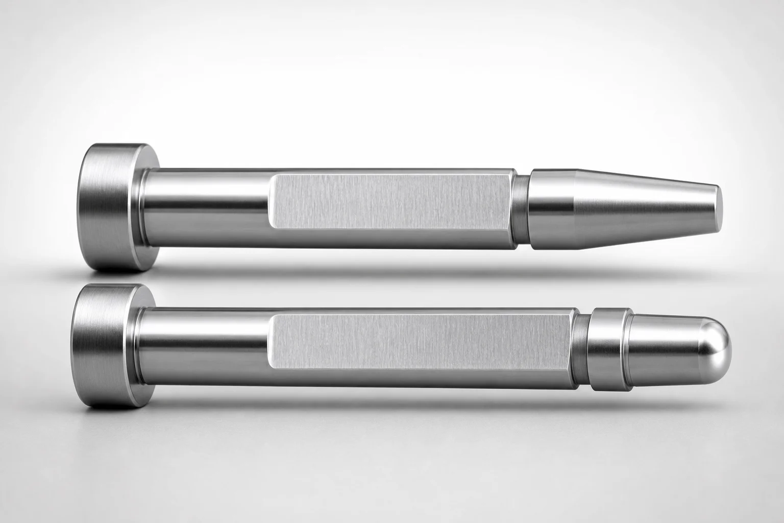
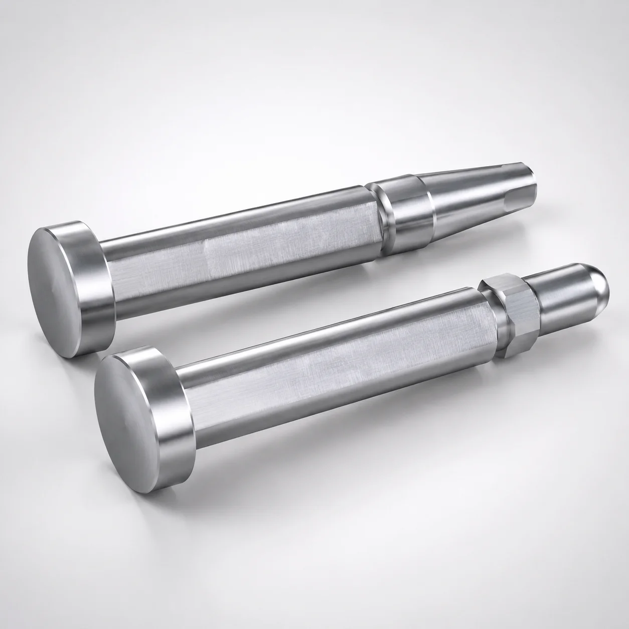
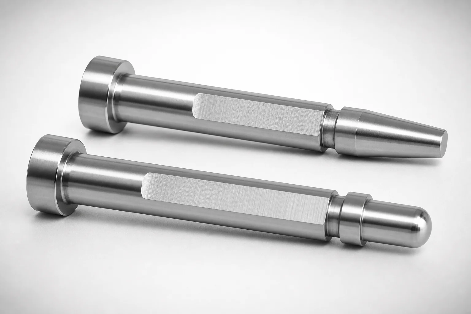
Need Custom Specifications?
Our engineering team can help with custom configurations, material selection, and volume pricing.