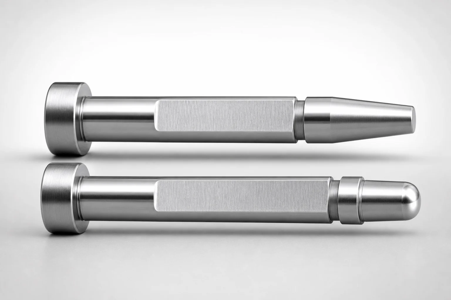
M2 Steel Gas Release One-Step Core Pins Flat-Sided
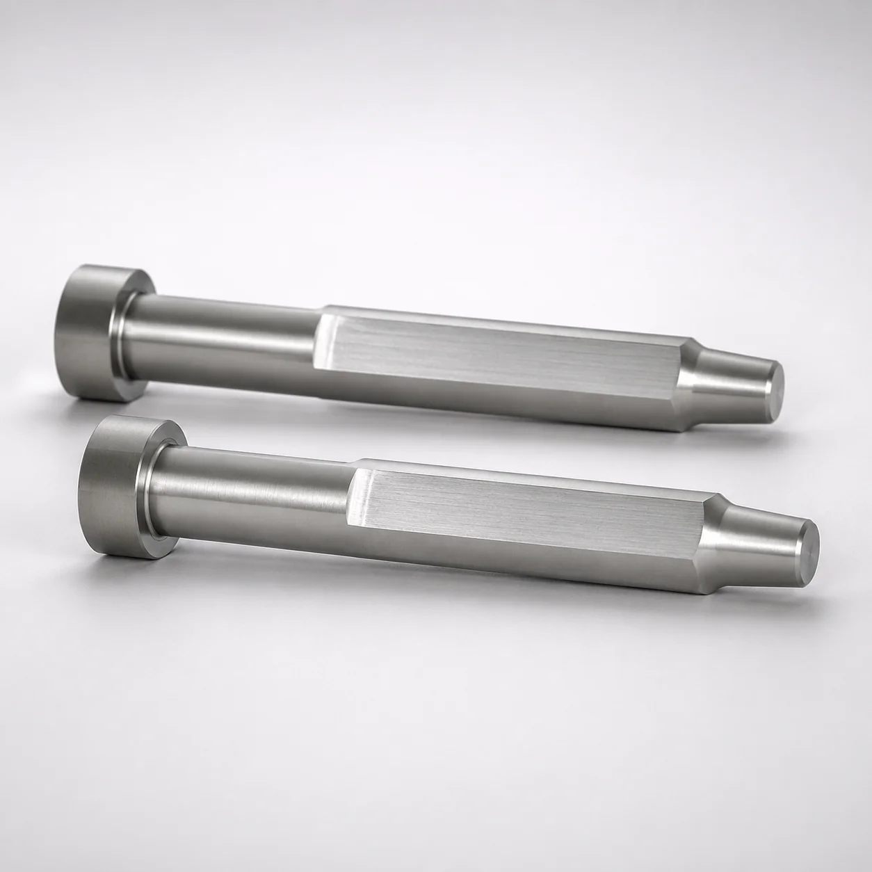
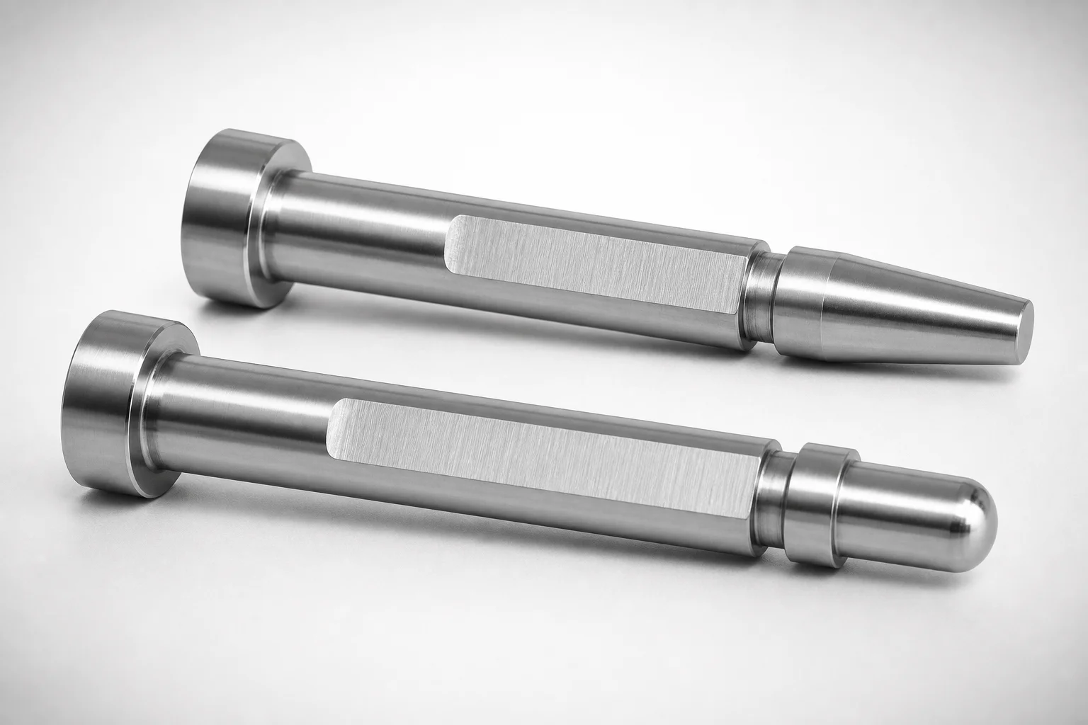
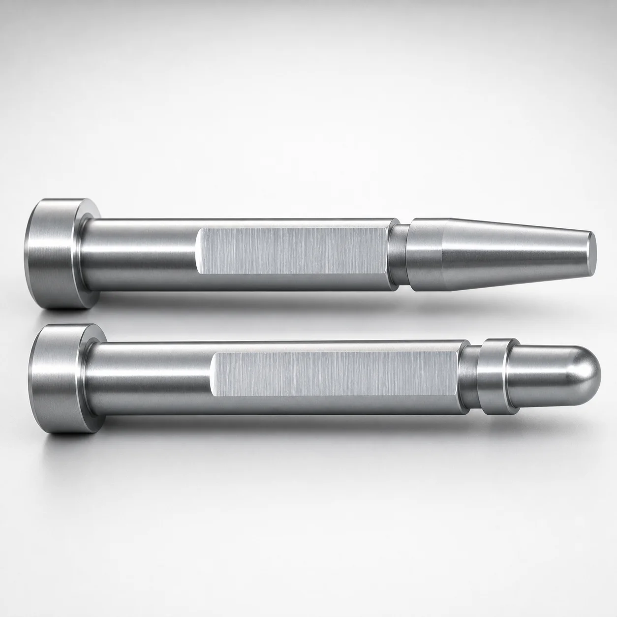
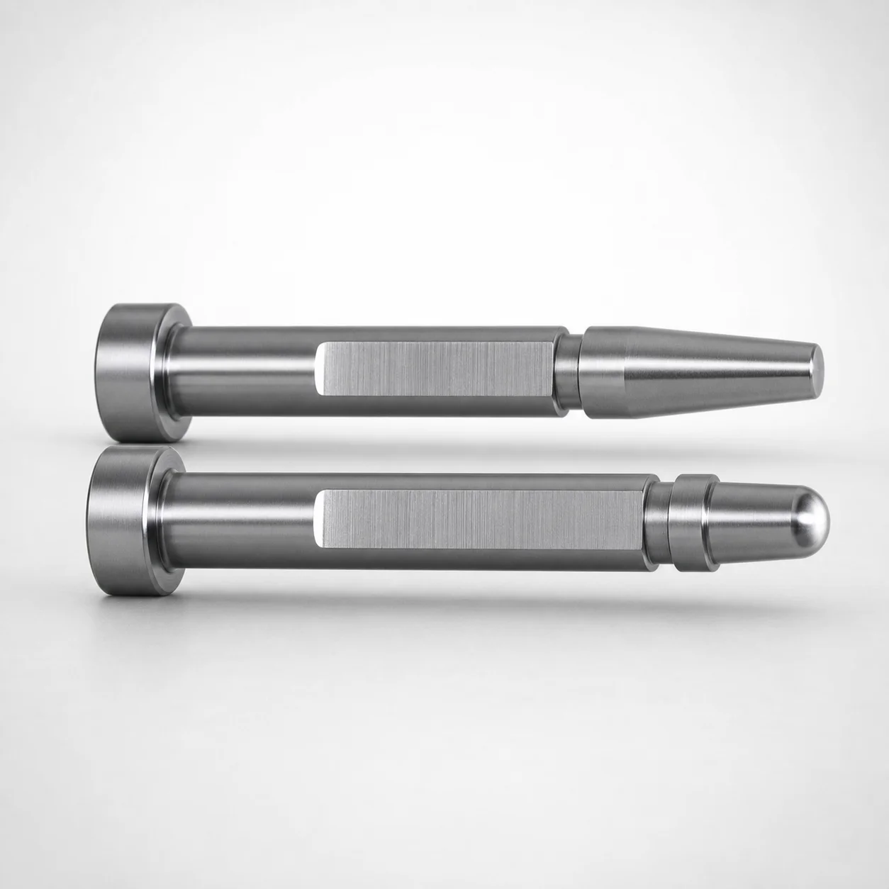
Gas release one-step core pins (M2 steel) provide a compact one-step gas vent design to support efficient mold exhaust. The Flat-Sided anti-rotation head helps maintain consistent positioning for repeatable ejection performance.
- One-step gas vent geometry improves exhaust during molding cycles
- SKH51 hardened steel construction delivers strong wear resistance under load
- Supports tight feature control, including tip gradient ±0.005 for stable alignment
- Designed to match precision die core applications where locating stability is critical
Specifications
11520 configurations available
| L Dimension Tolerance | D/P (Shaft Diameter) (mm) | First Step Shape | Tip Shape | No. (Nominal diameter) (mm) | A (Step shape diameter) (mm) | C (Step type taper width) (mm) | CVC (Designation of C dimension in increments of 0.01mm) (mm) | DC (Gas release section diameter) (mm) | Extend the flat section SV to the bottom | F (Bearing bore length) (mm) | FC (Makes F dimension shorter than F min) (mm) | G (Tip C chamfering width) (mm) | K (Tip angle) (°) | L (L dimension) (mm) | N (Gas release section diameter) (mm) | PC (Gas release section diameter) (mm) | Q (Tip R chamfering) (mm) | S (Tip tapered width) (mm) | SV (Gas release facet cutting length) (mm) | V (Tip diameter) (mm) | VC (V dimension alteration, smaller than V min) (mm) | When DC = D, DCX is applied | When PC=P, PCX is applied | type |
|---|---|---|---|---|---|---|---|---|---|---|---|---|---|---|---|---|---|---|---|---|---|---|---|---|
| +0.01/0 | 1 | 1A | No processing | - | - | - | - | 0.92 ~ 0.999 | - | 14.5 ~ 59.5 | - | - | - | 6.5 ~ 60 | 0.3 ~ 10 | - | - | - | 2 ~ 50 | 0.5 ~ 0.995 | - | - | - | - |
| +0.01/0 | 1 | 1A | No processing | - | - | - | - | 0.92 ~ 0.999 | SVC | 14.5 ~ 59.5 | - | - | - | 6.5 ~ 60 | 0.3 ~ 10 | - | - | - | - | 0.5 ~ 0.995 | - | - | - | - |
| +0.01/0 | 1 | 1A | No processing | - | - | - | - | - | - | 14.5 ~ 59.5 | - | - | - | 6.5 ~ 60 | 0.3 ~ 10 | - | - | - | 2 ~ 50 | 0.5 ~ 0.995 | - | DCX | - | - |
| +0.01/0 | 1 | 1A | No processing | - | - | - | - | - | SVC | 14.5 ~ 59.5 | - | - | - | 6.5 ~ 60 | 0.3 ~ 10 | - | - | - | - | 0.5 ~ 0.995 | - | DCX | - | - |
| +0.01/0 | 1 | 1A | No processing | - | - | - | - | 0.92 ~ 0.999 | - | 14.5 ~ 59.5 | - | - | - | 6.5 ~ 60 | 0.3 ~ 10 | - | - | - | 2 ~ 50 | - | 0.4 ~ 0.495 | - | - | - |
| +0.01/0 | 1 | 1A | No processing | - | - | - | - | 0.92 ~ 0.999 | SVC | 14.5 ~ 59.5 | - | - | - | 6.5 ~ 60 | 0.3 ~ 10 | - | - | - | - | - | 0.4 ~ 0.495 | - | - | - |
| +0.01/0 | 1 | 1A | No processing | - | - | - | - | - | - | 14.5 ~ 59.5 | - | - | - | 6.5 ~ 60 | 0.3 ~ 10 | - | - | - | 2 ~ 50 | - | 0.4 ~ 0.495 | DCX | - | - |
| +0.01/0 | 1 | 1A | No processing | - | - | - | - | - | SVC | 14.5 ~ 59.5 | - | - | - | 6.5 ~ 60 | 0.3 ~ 10 | - | - | - | - | - | 0.4 ~ 0.495 | DCX | - | - |
| +0.01/0 | 1 | 1A | No processing | - | - | - | - | 0.92 ~ 0.999 | - | - | 5 ~ 14.49 | - | - | 6.5 ~ 60 | 0.3 ~ 10 | - | - | - | 2 ~ 50 | 0.5 ~ 0.995 | - | - | - | - |
| +0.01/0 | 1 | 1A | No processing | - | - | - | - | 0.92 ~ 0.999 | SVC | - | 5 ~ 14.49 | - | - | 6.5 ~ 60 | 0.3 ~ 10 | - | - | - | - | 0.5 ~ 0.995 | - | - | - | - |
| +0.01/0 | 1 | 1A | No processing | - | - | - | - | - | - | - | 5 ~ 14.49 | - | - | 6.5 ~ 60 | 0.3 ~ 10 | - | - | - | 2 ~ 50 | 0.5 ~ 0.995 | - | DCX | - | - |
| +0.01/0 | 1 | 1A | No processing | - | - | - | - | - | SVC | - | 5 ~ 14.49 | - | - | 6.5 ~ 60 | 0.3 ~ 10 | - | - | - | - | 0.5 ~ 0.995 | - | DCX | - | - |
| +0.01/0 | 1 | 1A | No processing | - | - | - | - | 0.92 ~ 0.999 | - | - | 5 ~ 14.49 | - | - | 6.5 ~ 60 | 0.3 ~ 10 | - | - | - | 2 ~ 50 | - | 0.4 ~ 0.495 | - | - | - |
| +0.01/0 | 1 | 1A | No processing | - | - | - | - | 0.92 ~ 0.999 | SVC | - | 5 ~ 14.49 | - | - | 6.5 ~ 60 | 0.3 ~ 10 | - | - | - | - | - | 0.4 ~ 0.495 | - | - | - |
| +0.01/0 | 1 | 1A | No processing | - | - | - | - | - | - | - | 5 ~ 14.49 | - | - | 6.5 ~ 60 | 0.3 ~ 10 | - | - | - | 2 ~ 50 | - | 0.4 ~ 0.495 | DCX | - | - |
| +0.01/0 | 1 | 1A | No processing | - | - | - | - | - | SVC | - | 5 ~ 14.49 | - | - | 6.5 ~ 60 | 0.3 ~ 10 | - | - | - | - | - | 0.4 ~ 0.495 | DCX | - | - |
| +0.01/0 | 1.5 | 1A | No processing | - | - | - | - | 1.42 ~ 1.499 | - | 14.5 ~ 59.5 | - | - | - | 6.5 ~ 60 | 0.3 ~ 10 | - | - | - | 2 ~ 50 | 0.5 ~ 1.495 | - | - | - | - |
| +0.01/0 | 1.5 | 1A | No processing | - | - | - | - | 1.42 ~ 1.499 | SVC | 14.5 ~ 59.5 | - | - | - | 6.5 ~ 60 | 0.3 ~ 10 | - | - | - | - | 0.5 ~ 1.495 | - | - | - | - |
| +0.01/0 | 1.5 | 1A | No processing | - | - | - | - | - | - | 14.5 ~ 59.5 | - | - | - | 6.5 ~ 60 | 0.3 ~ 10 | - | - | - | 2 ~ 50 | 0.5 ~ 1.495 | - | DCX | - | - |
| +0.01/0 | 1.5 | 1A | No processing | - | - | - | - | - | SVC | 14.5 ~ 59.5 | - | - | - | 6.5 ~ 60 | 0.3 ~ 10 | - | - | - | - | 0.5 ~ 1.495 | - | DCX | - | - |
| +0.01/0 | 1.5 | 1A | No processing | - | - | - | - | 1.42 ~ 1.499 | - | 14.5 ~ 59.5 | - | - | - | 6.5 ~ 60 | 0.3 ~ 10 | - | - | - | 2 ~ 50 | - | 0.4 ~ 0.495 | - | - | - |
| +0.01/0 | 1.5 | 1A | No processing | - | - | - | - | 1.42 ~ 1.499 | SVC | 14.5 ~ 59.5 | - | - | - | 6.5 ~ 60 | 0.3 ~ 10 | - | - | - | - | - | 0.4 ~ 0.495 | - | - | - |
| +0.01/0 | 1.5 | 1A | No processing | - | - | - | - | - | - | 14.5 ~ 59.5 | - | - | - | 6.5 ~ 60 | 0.3 ~ 10 | - | - | - | 2 ~ 50 | - | 0.4 ~ 0.495 | DCX | - | - |
| +0.01/0 | 1.5 | 1A | No processing | - | - | - | - | - | SVC | 14.5 ~ 59.5 | - | - | - | 6.5 ~ 60 | 0.3 ~ 10 | - | - | - | - | - | 0.4 ~ 0.495 | DCX | - | - |
| +0.01/0 | 1.5 | 1A | No processing | - | - | - | - | 1.42 ~ 1.499 | - | - | 5 ~ 14.49 | - | - | 6.5 ~ 60 | 0.3 ~ 10 | - | - | - | 2 ~ 50 | 0.5 ~ 1.495 | - | - | - | - |
| +0.01/0 | 1.5 | 1A | No processing | - | - | - | - | 1.42 ~ 1.499 | SVC | - | 5 ~ 14.49 | - | - | 6.5 ~ 60 | 0.3 ~ 10 | - | - | - | - | 0.5 ~ 1.495 | - | - | - | - |
| +0.01/0 | 1.5 | 1A | No processing | - | - | - | - | - | - | - | 5 ~ 14.49 | - | - | 6.5 ~ 60 | 0.3 ~ 10 | - | - | - | 2 ~ 50 | 0.5 ~ 1.495 | - | DCX | - | - |
| +0.01/0 | 1.5 | 1A | No processing | - | - | - | - | - | SVC | - | 5 ~ 14.49 | - | - | 6.5 ~ 60 | 0.3 ~ 10 | - | - | - | - | 0.5 ~ 1.495 | - | DCX | - | - |
| +0.01/0 | 1.5 | 1A | No processing | - | - | - | - | 1.42 ~ 1.499 | - | - | 5 ~ 14.49 | - | - | 6.5 ~ 60 | 0.3 ~ 10 | - | - | - | 2 ~ 50 | - | 0.4 ~ 0.495 | - | - | - |
| +0.01/0 | 1.5 | 1A | No processing | - | - | - | - | 1.42 ~ 1.499 | SVC | - | 5 ~ 14.49 | - | - | 6.5 ~ 60 | 0.3 ~ 10 | - | - | - | - | - | 0.4 ~ 0.495 | - | - | - |
| +0.01/0 | 1.5 | 1A | No processing | - | - | - | - | - | - | - | 5 ~ 14.49 | - | - | 6.5 ~ 60 | 0.3 ~ 10 | - | - | - | 2 ~ 50 | - | 0.4 ~ 0.495 | DCX | - | - |
| +0.01/0 | 1.5 | 1A | No processing | - | - | - | - | - | SVC | - | 5 ~ 14.49 | - | - | 6.5 ~ 60 | 0.3 ~ 10 | - | - | - | - | - | 0.4 ~ 0.495 | DCX | - | - |
| +0.01/0 | 2 | 1A | No processing | - | - | - | - | 1.92 ~ 1.999 | - | 14.5 ~ 59.5 | - | - | - | 6.5 ~ 60 | 0.3 ~ 10 | - | - | - | 2 ~ 50 | 0.5 ~ 1.995 | - | - | - | - |
| +0.01/0 | 2 | 1A | No processing | - | - | - | - | 1.92 ~ 1.999 | SVC | 14.5 ~ 59.5 | - | - | - | 6.5 ~ 60 | 0.3 ~ 10 | - | - | - | - | 0.5 ~ 1.995 | - | - | - | - |
| +0.01/0 | 2 | 1A | No processing | - | - | - | - | - | - | 14.5 ~ 59.5 | - | - | - | 6.5 ~ 60 | 0.3 ~ 10 | - | - | - | 2 ~ 50 | 0.5 ~ 1.995 | - | DCX | - | - |
| +0.01/0 | 2 | 1A | No processing | - | - | - | - | - | SVC | 14.5 ~ 59.5 | - | - | - | 6.5 ~ 60 | 0.3 ~ 10 | - | - | - | - | 0.5 ~ 1.995 | - | DCX | - | - |
| +0.01/0 | 2 | 1A | No processing | - | - | - | - | 1.92 ~ 1.999 | - | - | 5 ~ 14.49 | - | - | 6.5 ~ 60 | 0.3 ~ 10 | - | - | - | 2 ~ 50 | 0.5 ~ 1.995 | - | - | - | - |
| +0.01/0 | 2 | 1A | No processing | - | - | - | - | 1.92 ~ 1.999 | SVC | - | 5 ~ 14.49 | - | - | 6.5 ~ 60 | 0.3 ~ 10 | - | - | - | - | 0.5 ~ 1.995 | - | - | - | - |
| +0.01/0 | 2 | 1A | No processing | - | - | - | - | - | - | - | 5 ~ 14.49 | - | - | 6.5 ~ 60 | 0.3 ~ 10 | - | - | - | 2 ~ 50 | 0.5 ~ 1.995 | - | DCX | - | - |
| +0.01/0 | 2 | 1A | No processing | - | - | - | - | - | SVC | - | 5 ~ 14.49 | - | - | 6.5 ~ 60 | 0.3 ~ 10 | - | - | - | - | 0.5 ~ 1.995 | - | DCX | - | - |
| +0.01/0 | 2.5 | 1A | No processing | - | - | - | - | 2.42 ~ 2.499 | - | 14.5 ~ 59.5 | - | - | - | 6.5 ~ 60 | 0.3 ~ 10 | - | - | - | 2 ~ 50 | 0.5 ~ 2.495 | - | - | - | - |
| +0.01/0 | 2.5 | 1A | No processing | - | - | - | - | 2.42 ~ 2.499 | SVC | 14.5 ~ 59.5 | - | - | - | 6.5 ~ 60 | 0.3 ~ 10 | - | - | - | - | 0.5 ~ 2.495 | - | - | - | - |
| +0.01/0 | 2.5 | 1A | No processing | - | - | - | - | - | - | 14.5 ~ 59.5 | - | - | - | 6.5 ~ 60 | 0.3 ~ 10 | - | - | - | 2 ~ 50 | 0.5 ~ 2.495 | - | DCX | - | - |
| +0.01/0 | 2.5 | 1A | No processing | - | - | - | - | - | SVC | 14.5 ~ 59.5 | - | - | - | 6.5 ~ 60 | 0.3 ~ 10 | - | - | - | - | 0.5 ~ 2.495 | - | DCX | - | - |
| +0.01/0 | 2.5 | 1A | No processing | - | - | - | - | 2.42 ~ 2.499 | - | - | 5 ~ 14.49 | - | - | 6.5 ~ 60 | 0.3 ~ 10 | - | - | - | 2 ~ 50 | 0.5 ~ 2.495 | - | - | - | - |
| +0.01/0 | 2.5 | 1A | No processing | - | - | - | - | 2.42 ~ 2.499 | SVC | - | 5 ~ 14.49 | - | - | 6.5 ~ 60 | 0.3 ~ 10 | - | - | - | - | 0.5 ~ 2.495 | - | - | - | - |
| +0.01/0 | 2.5 | 1A | No processing | - | - | - | - | - | - | - | 5 ~ 14.49 | - | - | 6.5 ~ 60 | 0.3 ~ 10 | - | - | - | 2 ~ 50 | 0.5 ~ 2.495 | - | DCX | - | - |
| +0.01/0 | 2.5 | 1A | No processing | - | - | - | - | - | SVC | - | 5 ~ 14.49 | - | - | 6.5 ~ 60 | 0.3 ~ 10 | - | - | - | - | 0.5 ~ 2.495 | - | DCX | - | - |
| +0.01/0 | 3 | 1A | No processing | - | - | - | - | 2.92 ~ 2.999 | - | 14.5 ~ 59.5 | - | - | - | 6.5 ~ 60 | 0.3 ~ 10 | - | - | - | 2 ~ 50 | 0.7 ~ 2.995 | - | - | - | - |
| +0.01/0 | 3 | 1A | No processing | - | - | - | - | 2.92 ~ 2.999 | SVC | 14.5 ~ 59.5 | - | - | - | 6.5 ~ 60 | 0.3 ~ 10 | - | - | - | - | 0.7 ~ 2.995 | - | - | - | - |
Product Guide
Application Scenarios+
These M2 steel gas release one-step core pins are used in injection mold tooling to create a compact venting feature in a single locating/ejection component. The flat-sided, anti-rotation head improves stable positioning in the core insert so the gas-release geometry stays aligned through repeated thermal cycles and high cycle counts.
- Automotive & electrical connector molds: Suitable for polymer housings and small connector components where trapped air near deep ribs or thin-gated areas can cause burn marks. The one-step gas vent supports efficient exhaust during molding and helps maintain consistent ejection performance.
- Medical device housings and precision covers: Beneficial when dimensional repeatability and reliable ejection are required. The flat-sided geometry helps prevent rotational drift, supporting repeatable core pin travel and part surface quality.
- Consumer device and appliance inserts: Works well in compact tooling layouts that need integrated venting without adding separate vent hardware, reducing assembly complexity.
Overall, the anti-rotation design and hardened M2-grade construction make this variant well suited for precision cores that demand both stable locating and wear resistance.
Material & Process Details+
This product uses M2 steel identified in the spec as SKH51 hardened steel. SKH51 is commonly correlated with AISI M2 high-speed steel, providing strong wear resistance for small, highly loaded mold components.
- Hardness: The hardened condition is intended for high abrasion resistance; practical use targets the typical M2 hardness range (often around HRC 60–65) depending on final heat treatment.
- Heat treatment: Supplied as a hardened steel pin, typically achieved via quench-and-temper processing to balance hardness and toughness for repeated sliding/contact during ejection and gas-release operation.
- Trade-offs: Higher hardness improves wear life and tip stability, while adequate tempering is needed to avoid excessive brittleness at sharp tips and thin features.
Compared with less hard tool steels, SKH51/M2 grade offers better resistance to fretting and abrasive wear, which is important for precision core pin geometries with venting sections.
Sizing & Selection Guide+
Select dimensions by matching the pin’s venting and locating geometry to the core/cavity layout. Start with the shaft diameter D/P (0.8 ~ 13 mm) and the corresponding nominal diameter 1 ~ 13 mm to ensure the pin fits the mold’s bushing/hole size without interference.
- Length (L = 6.5 ~ 60 mm): Choose L to cover the required core engagement depth and full ejection stroke clearance. If your mold stack-up changes, confirm L supports the needed retention while maintaining vent exposure.
- Gas release section: Use DC (0.92 ~ 12.92 mm) and the corresponding N (0.3 ~ 10 / 0.5 ~ 15 mm) family to align vent diameter to your venting target. Note that PC (0.72 ~ 9.92 mm) is applied in specific conditions: when PC = P (PCX).
- Tolerance considerations: The L dimension tolerance is +0.01/0, 0/-0.05, so verify whether you need tight positional control at the ejection stroke end. Where profiles use the flat section setting SVC, ensure the housing keying/anti-rotation clearance supports correct orientation.
Finally, confirm tip gradient control such as tip gradient ±0.005 is consistent with your alignment requirements, especially for precision vent placement.
Frequently Asked Questions
Which shaft diameter range (D/P) and nominal diameter values are available for this gas release one-step core pin?+
This series covers D/P (shaft diameter) from 0.8 to 13 mm and nominal diameter 1 to 13 mm. Select the shaft diameter first to match your mold’s core pin bore and support bushing sizing. Then validate that the available L length range supports your stack-up and ejection stroke.
How do I choose the gas vent geometry using DC and N, and when are the DCX/PCX variations applied?+
Use DC (gas release section diameter) 0.92 to 12.92 mm together with the appropriate N option (0.3–10 or 0.5–15 mm) to target the required venting cross-section. The design includes conditional variants: when DC = D, DCX is applied; when PC = P, PCX is applied. Confirm your intended vent diameter relationships before finalizing the drawing.
What tolerance applies to the L (length) dimension and what does that mean for ejection stroke alignment?+
The L dimension tolerance is +0.01/0, 0/-0.05. This means the pin length may be slightly longer than nominal (+0.01) but can also be shorter down to -0.05, depending on the tolerance band. For tight end-of-stroke alignment, review whether your stack-up requires the pin to be at or near the upper limit.
What tip and step shape options are available, and how do they affect alignment and vent performance?+
First step shapes are available as 1A, 1B, 1C, 1D, while the tip shape can be selected from No processing, B, C, G, R, T. These profile options change the venting/tip contact geometry and can influence how the pin enters and exits the core feature. If anti-rotation positioning is critical, ensure the flat-sided head is compatible with your mold’s keying/orientation scheme.
Does the flat-sided anti-rotation geometry require special orientation features in the mold?+
Yes. The flat-sided head is designed to prevent rotation, so the mold should provide a corresponding locating/keying arrangement to maintain the intended orientation of the gas-release feature. Use the fixed configuration SVC (flat section SV extended to the bottom) as specified to ensure the anti-rotation facet engages correctly within the core housing.
Related Products
Need Custom Specifications?
Our engineering team can help with custom configurations, material selection, and volume pricing.