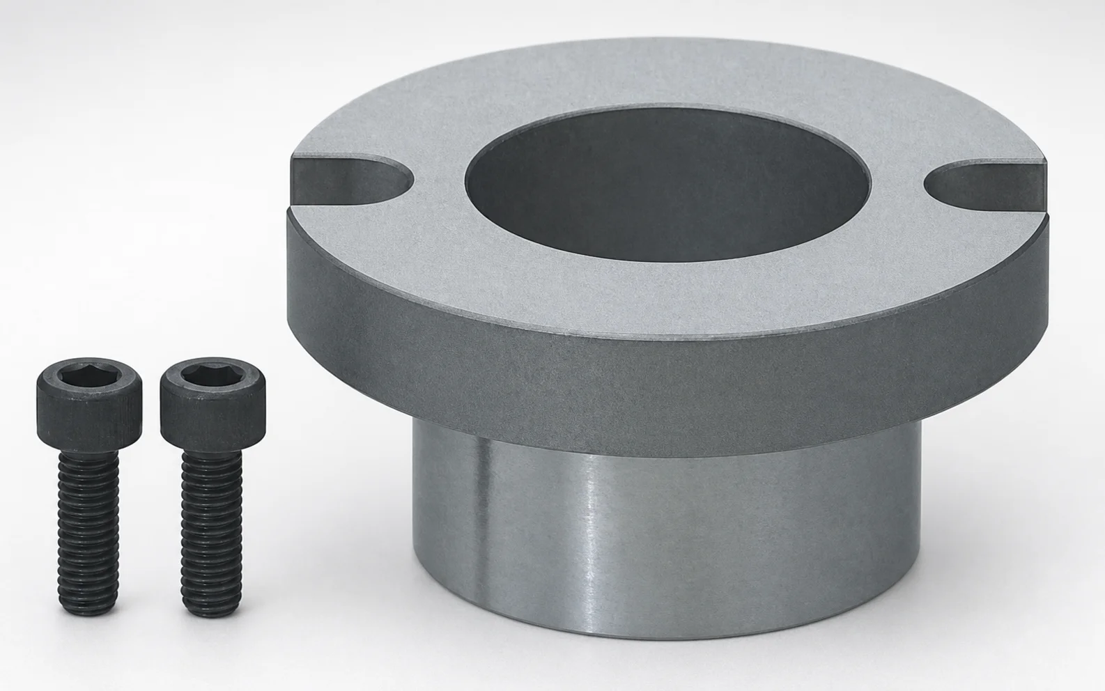
DIN Standard 52100 Steel Sprue Bushing Guides SBGN Type
Sprue bushing guides (52100 steel) with SBGN type construction provide reliable positioning for sprue bushings during mold assembly. They support smooth guidance and consistent feed alignment in production.
- SBGN type sprue bushing guide design for stable alignment and repeatable assembly
- 52100 steel for strong wear resistance under continuous molding cycles
- Engineered for consistent fits to help maintain smooth guidance and reduce assembly variation
- Suitable for sprue bushing guide applications in standard mold systems
Specifications
6 configurations available
| Head Thickness (mm) | D (Shaft Diameter) (mm) | G (Taper angle) (mm) | L (L dimension) (mm) | V (Inner diameter) (mm) | type |
|---|---|---|---|---|---|
| 8 | 16 | 1 ~ 10 | 15 ~ 30 | 6 ~ 9 | - |
| 8 | 20 | 1 ~ 10 | 15 ~ 30 | 9 ~ 12 | - |
| 8 | 25 | 1 ~ 10 | 15 ~ 30 | 12 ~ 15 | - |
| 10 | 28 | 1 ~ 10 | 20 ~ 30 | 16 ~ 19 | - |
| 10 | 35 | 1 ~ 10 | 25 ~ 40 | 21 ~ 24 | - |
| 10 | 40 | 1 ~ 10 | 25 ~ 40 | 26 ~ 29 | - |
Product Guide
Application Scenarios+
Sprue bushing guide components like this SBGN type are used to precisely position sprue bushings during injection mold assembly, ensuring repeatable alignment from clamp-up to cycle-to-cycle flow. Their primary value is stable guidance when the sprue bushing experiences repeated load and thermal cycling.
- Automotive connector and housing molds: Use the SBGN geometry to maintain consistent sprue alignment, helping prevent feed variation that can impact gate formation and part-to-part repeatability.
- High-volume consumer and appliance injection molds: The 52100 steel guide support is suited for long wear in continuous production where rapid assembly cycles and abrasive sprue contact points demand durable wear surfaces.
- Multi-cavity or family mold systems: Guides with consistent fit help reduce stack-up variation across cavities, improving uniform runner/sprue engagement and simplifying setup.
The combination of SBGN type alignment design and 52100 steel wear resistance makes this variant well-suited for molds where assembly repeatability and steady sprue centering are critical.
Material & Process Details+
This guide is specified in 52100 steel, a high-carbon chromium bearing steel commonly selected for wear-critical mold interfaces. In industrial equivalent terms, 52100 is often referenced as AISI 52100, and it is typically treated to achieve high surface hardness for sliding and guidance duty.
- Wear resistance: The hardened 52100 condition provides strong resistance to galling and abrasive wear from repeated sprue bushing guidance contact.
- Hardness/heat treatment state: Exact HRC and heat-treatment process parameters are not provided in the supplied data; however, 52100 guide components are typically delivered in a hardened, quenched-and-tempered condition to balance surface hardness and dimensional stability.
- Toughness trade-off: Higher hardness improves wear performance but can reduce toughness if over-hardened; proper quench/temper control is therefore important for shock resistance during mold assembly.
If alternative steels are offered, they generally trade off wear resistance versus toughness—52100 is chosen when guidance wear dominates the service behavior.
Sizing & Selection Guide+
To select the correct sprue bushing guide, match the shaft diameter (D) and the inner diameter (V) to the sprue bushing and guide engagement requirements in your mold design. The available D sizes are 16, 20, 25, 28, 35, 40 mm.
- Check V (inner diameter): Choose the V range that fits your sprue bushing interface: 6–9, 9–12, 12–15, 16–19, 21–24, 26–29 mm.
- Select length L: Available L options are 15–30, 20–30, or 25–40 mm depending on the size variant. Ensure L provides sufficient guidance contact length without interfering with adjacent tooling.
- Taper angle G: Fixed as 1 to 10 (mm-stated range as provided), so compatibility is mainly determined by your mating sprue bushing taper geometry.
- Head thickness: Available 8 or 10 mm; verify the head thickness matches pocket depth and retention design.
Confirm fit by considering assembly clearances and any expected thermal expansion; since tolerance data is not provided, use your standard mold-builder clearance conventions for hardened guidance surfaces.
Frequently Asked Questions
Which D (shaft diameter) options are available for this SBGN sprue bushing guide, and how do I match them to my mold’s sprue bushing?+
How do I choose the correct V (inner diameter) range for stable sprue alignment?+
What head thickness options (8 or 10 mm) should I use in my guide pocket design?+
Is the taper angle G variable on this product, and what does the provided range mean for compatibility?+
What length L options are available, and how do I prevent too-short or too-long guidance contact?+
Related Products
Need Custom Specifications?
Our engineering team can help with custom configurations, material selection, and volume pricing.