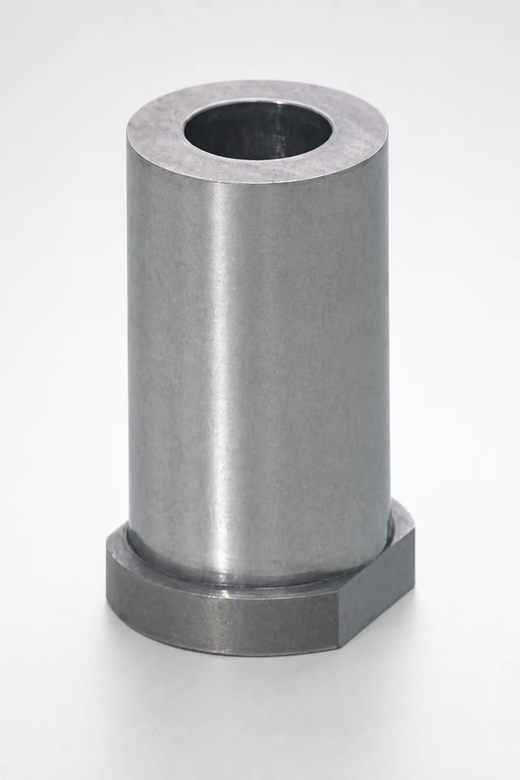
H13 Steel Sprue Lock Bushings Straight Headed
Sprue lock bushings straight headed (H13 steel) are engineered to maintain precise sprue alignment and stable positioning in injection molds. The straight tip and headed form help control guide engagement for consistent molding cycles.
- Straight tip matching supports repeatable sprue lock engagement
- H13 steel construction with hardened wear resistance for tool life
- Head thickness 4 mm improves locating stability during clamping
- Built for sprue bushing guide applications in molding systems
Specifications
22 configurations available
| Head Thickness (mm) | D (Shaft Diameter) (mm) | Specification | Shape | L (L dimension) (mm) | LC (L dimension alteration) (mm) | P (Ejector pin guide diameter) (mm) | S (Sprue lock section depth) (mm) | A (Taper angle) (°) | B (Distance from end face to recess) (mm) | type |
|---|---|---|---|---|---|---|---|---|---|---|
| 4 | 8 | B dimension designation type | Head type | 20 ~ 50 | - | 3 | 3 ~ 7 | 0 ~ 4 | 12 ~ 20 | - |
| 4 | 8 | B dimension designation type | Head type | - | 15 ~ 50 | 3 | 3 ~ 7 | 0 ~ 4 | 12 ~ 20 | - |
| 4 | 10 | B dimension designation type | Head type | 20 ~ 50 | - | 4 | 3 ~ 8 | 0 ~ 4 | 13 ~ 20 | - |
| 4 | 10 | B dimension designation type | Head type | - | 15 ~ 50 | 4 | 3 ~ 8 | 0 ~ 4 | 13 ~ 20 | - |
| 4 | 13 | B dimension designation type | Head type | 20 ~ 60 | - | 5 ~ 6 | 3 ~ 10 | 0 ~ 4 | 14 ~ 30 | - |
| 4 | 13 | B dimension designation type | Head type | - | 15 ~ 60 | 5 ~ 6 | 3 ~ 10 | 0 ~ 4 | 14 ~ 30 | - |
| 4 | 16 | B dimension designation type | Head type | 25 ~ 60 | - | 8 | 3 ~ 12 | 0 ~ 4 | 20 ~ 30 | - |
| 4 | 16 | B dimension designation type | Head type | - | 15 ~ 60 | 8 | 3 ~ 12 | 0 ~ 4 | 20 ~ 30 | - |
| 4 | 8 | B dimension selection type | Head type | 20 ~ 50 | - | 3 | 3 ~ 7 | 0 ~ 5 | - | - |
| 4 | 8 | B dimension selection type | Head type | - | 15 ~ 50 | 3 | 3 ~ 7 | 0 ~ 5 | - | - |
| 4 | 10 | B dimension selection type | Head type | 20 ~ 50 | - | 4 | 3 ~ 8 | 0 ~ 5 | - | - |
| 4 | 10 | B dimension selection type | Head type | - | 15 ~ 50 | 4 | 3 ~ 8 | 0 ~ 5 | - | - |
| 4 | 13 | B dimension selection type | Head type | 20 ~ 60 | - | 5 ~ 6 | 3 ~ 10 | 0 ~ 5 | - | - |
| 4 | 13 | B dimension selection type | Head type | - | 15 ~ 60 | 5 ~ 6 | 3 ~ 10 | 0 ~ 5 | - | - |
| 4 | 16 | B dimension selection type | Head type | 25 ~ 60 | - | 8 | 3 ~ 12 | 0 ~ 5 | - | - |
| 4 | 16 | B dimension selection type | Head type | - | 15 ~ 60 | 8 | 3 ~ 12 | 0 ~ 5 | - | - |
| - | 13 | B dimension selection type | Straight type | 25 | - | 3 ~ 4 | 3 ~ 8 | 0 ~ 5 | - | - |
| - | 13 | B dimension selection type | Straight type | - | 18 ~ 25 | 3 ~ 4 | 3 ~ 8 | 0 ~ 5 | - | - |
| - | 16 | B dimension selection type | Straight type | 30 ~ 35 | - | 5 ~ 6 | 3 ~ 10 | 0 ~ 5 | - | - |
| - | 16 | B dimension selection type | Straight type | - | 20 ~ 35 | 5 ~ 6 | 3 ~ 10 | 0 ~ 5 | - | - |
| - | 20 | B dimension selection type | Straight type | 40 | - | 8 | 3 ~ 12 | 0 ~ 5 | - | - |
| - | 20 | B dimension selection type | Straight type | - | 24 ~ 40 | 8 | 3 ~ 12 | 0 ~ 5 | - | - |
Product Guide
Application Scenarios+
These sprue lock bushings are used in injection mold tooling to ensure repeatable sprue alignment between the runner/sprue system and the mating components. The straight headed configuration supports stable engagement during the final clamp stroke, helping prevent drift that can lead to misalignment, flash, or inconsistent filling.
- Automotive connector and small-part molds: Ideal where short cycle time and tight alignment repeatability are required. The 4 mm head thickness improves locating stability during clamping, while the straight tip promotes consistent guide engagement each shot.
- Electronics enclosures and precision housings: Suitable for molding systems that benefit from controlled sprue entry. H13 steel wear resistance supports longer tooling life under repeated mechanical contact in sprue lock regions.
- General sprue bushing guide applications: Supports tool designs that rely on a defined sprue lock section depth (S) and taper angle (A) to manage insertion and seating repeatably across varying part geometries.
Material & Process Details+
H13 steel is selected for sprue lock bushings due to its balance of hot-work capability and wear resistance under repeated contact. In tool steels, H13 is widely associated with the AISI H13 / equivalent to SKD61 family, making it a practical choice for injection tooling components that experience mechanical loading and thermal cycling.
Typical performance targets for H13 include high hardness after hardening and tempering, with improved wear resistance at the expense of some toughness compared with softer grades. For best repeatability in sprue alignment surfaces, the bushing should be treated by quenching and tempering to achieve the desired hardness (often specified to design for high-contact resistance) rather than remaining in a fully pre-hardened condition.
- Wear resistance: High after heat treatment for longer service in lock engagement zones.
- Toughness trade-off: Increasing hardness can reduce impact toughness; tempering is used to restore toughness while maintaining wear resistance.
- Alternative materials (brief): If you require lower cost or different wear/toughness balance, hardened low-alloy steels may be used, but they typically have shorter life under repeated alignment contact than H13.
Sizing & Selection Guide+
Select dimensions by matching the bushing to the mold’s sprue lock interface, then verify the guide engagement geometry for your clamp stroke and runner alignment. This product provides a fixed head thickness of 4 mm and multiple variable options for shaft diameter, length, and lock geometry.
- Shaft diameter (D): Choose from 8, 10, 13, 16, 20 mm to correspond to your sprue guide bore/ejector guide requirements (P is also available in 3, 4, 5–6, 8, 3–4 mm depending on the configuration).
- Length (L): Use one of the ranges 20–50, 20–60, 25–60, 25, 30, 30–35, 40 (as offered by the specific selection) to fit your tool thickness and alignment zone.
- Lock and positioning: Match S (3–7 to 3–12 mm), taper angle A (0–4° or 0–5°), and B (12–20 to 20–30 mm) to control insertion and seating depth.
Check tolerance/fit at the recess and guide diameters (notably B and P-related areas) so engagement is repeatable without binding. Where dimensions are marked as variable (B selection type, B dimension designation type), confirm the exact configured option before machining the receiving features.
Frequently Asked Questions
Which shaft diameter (D) options are available for H13 sprue lock bushings straight headed, and how does D affect fit with the mold guide bore?+
How do I select the correct head-to-recess distance (B) for repeatable sprue lock engagement?+
What is the purpose of the fixed 4 mm head thickness, and when does it matter most?+
What lock section depth (S) and taper angle (A) ranges are available for controlling insertion and seating?+
How should I choose the length (L) when multiple L ranges are listed (20–50 up to 25–60, plus discrete values)?+
Related Products
Need Custom Specifications?
Our engineering team can help with custom configurations, material selection, and volume pricing.