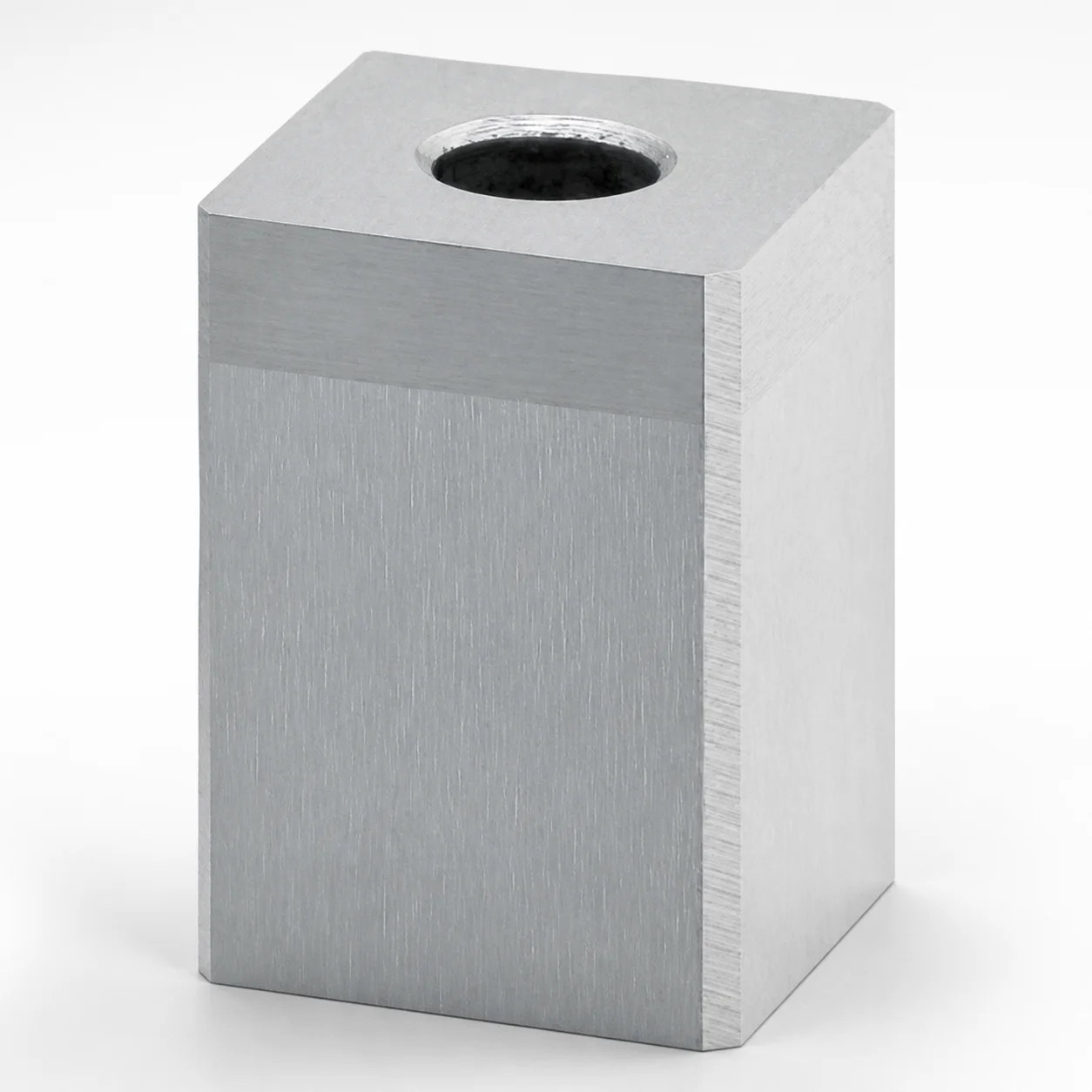
Punch Holders - Cavity Insert
Punch Holders - Cavity Insert provide precise support for cavity punch applications, improving alignment stability to help maintain machining accuracy and consistent forming results across production runs.
- Precision cavity insert design improves punch positioning stability for reliable alignment
- Built from durable SKD11-equivalent or SKH51-equivalent materials with wear-resistant performance
- Manufactured for controlled fit to support tight assembly in punch holder systems
- Compatible with round punch and shaped punch setups in high-demand tooling
Specifications
30 configurations available
| Material | L (L dimension) (mm) | V (Outer shape) (mm) | H (Outer shape) (mm) | Specification | D (Punch diameter) | LC (Full length alteration) (mm) | type |
|---|---|---|---|---|---|---|---|
| SKH51 Equivalent | 7 ~ 22 | 3 | 3 | For round punch | 1.6 | - | - |
| SKH51 Equivalent | - | 3 | 3 | For round punch | 1.6 | 7.01 ~ 24.91 | - |
| SKH51 Equivalent | 7 ~ 22 | 4 | 4 | For round punch | 1.6 ~ 2 | - | - |
| SKH51 Equivalent | - | 4 | 4 | For round punch | 1.6 ~ 2 | 7.01 ~ 24.91 | - |
| SKH51 Equivalent | 7 ~ 22 | 5 | 5 | For round punch | 2.5 | - | - |
| SKH51 Equivalent | - | 5 | 5 | For round punch | 2.5 | 7.1 ~ 21.9 | - |
| SKD11 Equivalent | 11 ~ 25 | 8 | 8 | For round punch | 3 ~ 4 | - | - |
| SKD11 Equivalent | - | 8 | 8 | For round punch | 3 ~ 4 | 11.01 ~ 24.91 | - |
| SKD11 Equivalent | 11 ~ 25 | 10 | 10 | For round punch | 3 ~ 5 | - | - |
| SKD11 Equivalent | - | 10 | 10 | For round punch | 3 ~ 5 | 11.01 ~ 24.91 | - |
| SKD11 Equivalent | 11 ~ 25 | 13 | 13 | For round punch | 4 ~ 8 | - | - |
| SKD11 Equivalent | - | 13 | 13 | For round punch | 4 ~ 8 | 11.01 ~ 24.91 | - |
| SKD11 Equivalent | 11 ~ 25 | 16 | 16 | For round punch | 8 ~ 10 | - | - |
| SKD11 Equivalent | - | 16 | 16 | For round punch | 8 ~ 10 | 11.01 ~ 24.91 | - |
| SKD11 Equivalent | 11 ~ 25 | 20 | 20 | For round punch | 10 ~ 13 | - | - |
| SKD11 Equivalent | - | 20 | 20 | For round punch | 10 ~ 13 | 11.1 ~ 24.9 | - |
| SKD11 Equivalent | 11 ~ 25 | 25 | 25 | For round punch | 13 ~ 16 | - | - |
| SKD11 Equivalent | - | 25 | 25 | For round punch | 13 ~ 16 | 11.01 ~ 24.91 | - |
| SKD11 Equivalent | 16 ~ 30 | 8 | 8 | For shaped punch | 3 ~ 4 | - | - |
| SKD11 Equivalent | - | 8 | 8 | For shaped punch | 3 ~ 4 | 16.01 ~ 29.91 | - |
| SKD11 Equivalent | 16 ~ 30 | 10 | 10 | For shaped punch | 3 ~ 5 | - | - |
| SKD11 Equivalent | - | 10 | 10 | For shaped punch | 3 ~ 5 | 16.01 ~ 29.91 | - |
| SKD11 Equivalent | 16 ~ 30 | 13 | 13 | For shaped punch | 4 ~ 8 | - | - |
| SKD11 Equivalent | - | 13 | 13 | For shaped punch | 4 ~ 8 | 16.01 ~ 29.91 | - |
| SKD11 Equivalent | 16 ~ 30 | 16 | 16 | For shaped punch | 8 ~ 10 | - | - |
| SKD11 Equivalent | - | 16 | 16 | For shaped punch | 8 ~ 10 | 16.01 ~ 29.91 | - |
| SKD11 Equivalent | 16 ~ 30 | 20 | 20 | For shaped punch | 10 ~ 13 | - | - |
| SKD11 Equivalent | - | 20 | 20 | For shaped punch | 10 ~ 13 | 16.01 ~ 29.91 | - |
| SKD11 Equivalent | 16 ~ 30 | 25 | 25 | For shaped punch | 13 ~ 16 | - | - |
| SKD11 Equivalent | - | 25 | 25 | For shaped punch | 13 ~ 16 | 16.01 ~ 29.91 | - |
Product Guide
Application Scenarios+
This cavity insert is used inside punch holder systems to support cavity punch applications where stable punch alignment directly affects forming quality and machining repeatability.
- Automotive and appliance forming: In progressive or fine-blank tooling, the insert helps maintain the punch axis for both round and shaped punches, reducing misalignment-driven wear and dimensional drift during long production runs.
- Electrical connector and terminal tooling: For shaped cavities, it provides controlled seating geometry that supports precise guidance of the punch tip, helping maintain consistent cavity fill and burr control.
- General stamping for custom shapes: When multiple punch geometries are used, the variant supports reliable location for the specified round or shaped punch type, improving setup accuracy during tool changeovers.
With its wear-focused SKD11-equivalent or SKH51-equivalent steel options and tight assembly-fit design, it is suited to environments requiring stable positioning and repeatable machining outcomes.
Material & Process Details+
These punch holders/cavity inserts are offered in two hardened tool-steel options: SKD11-equivalent and SKH51-equivalent, selected to balance wear resistance and toughness for different punch duty profiles.
- SKD11-equivalent: Commonly used when strong toughness is needed alongside good wear performance; it is typically supplied in a heat-treated condition and aims for stable cutting/impact resistance under stamping loads.
- SKH51-equivalent: Designed for higher wear resistance in abrasive or long-cycle conditions; its high-speed steel family chemistry improves red-hardness and edge durability compared with standard die steels.
Hardness is chosen for tooling service (commonly in the mid-to-high HRC range after heat treatment), where increased hardness improves wear resistance but can reduce toughness. The final microstructure after heat treatment (quenched and tempered for die steels; appropriate hardening/tempering for HSS-type options) governs the wear–toughness trade-off.
Sizing & Selection Guide+
Correct selection is driven by matching the insert geometry to the punch system and cavity/core requirements. Start by identifying whether your application uses a round punch or a shaped punch, then select the corresponding insert configuration.
- Punch diameter (D): Ensure your punch diameter is within 1.6 to 13 mm.
- Outer shape (V and H): Choose V in 3 to 25 mm and H in 3 to 25 mm to match the holder’s mating recess/profile.
- Length (L) and full-length alteration (LC): L is offered in ranges 7–22 mm, 11–25 mm, and 16–30 mm. Select LC from the available alternatives (e.g., 7.01–24.91 or 16.01–29.91 mm) to match depth and stack-up needs.
For reliable guidance, keep the assembly fit within the tooling’s specified tolerance scheme. Because these dimensions are product variants (not free-form), verify the exact size combination against your holder block cavity/core drawings and expected insertion clearance.
Frequently Asked Questions
Which material option (SKD11-equivalent vs SKH51-equivalent) is better for cavity punch inserts handling long production runs?+
How do I size the cavity insert to match a round punch of a given diameter?+
What dimensions should be checked first when using a shaped punch cavity insert?+
Are L and LC interchangeable, or do they serve different selection purposes in the punch holder assembly?+
What fit and tolerance considerations apply to stable punch alignment in these cavity insert applications?+
Related Products
Need Custom Specifications?
Our engineering team can help with custom configurations, material selection, and volume pricing.