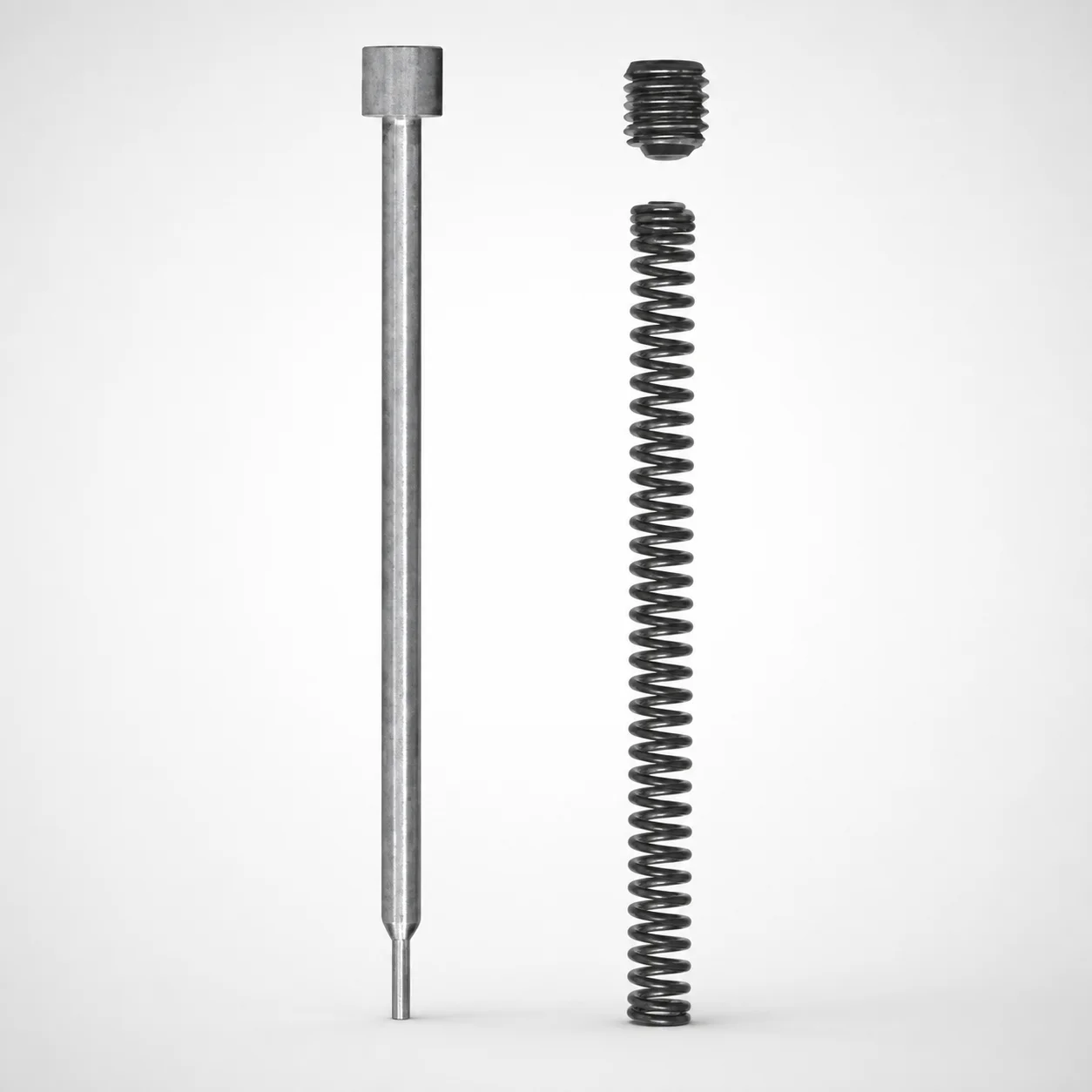
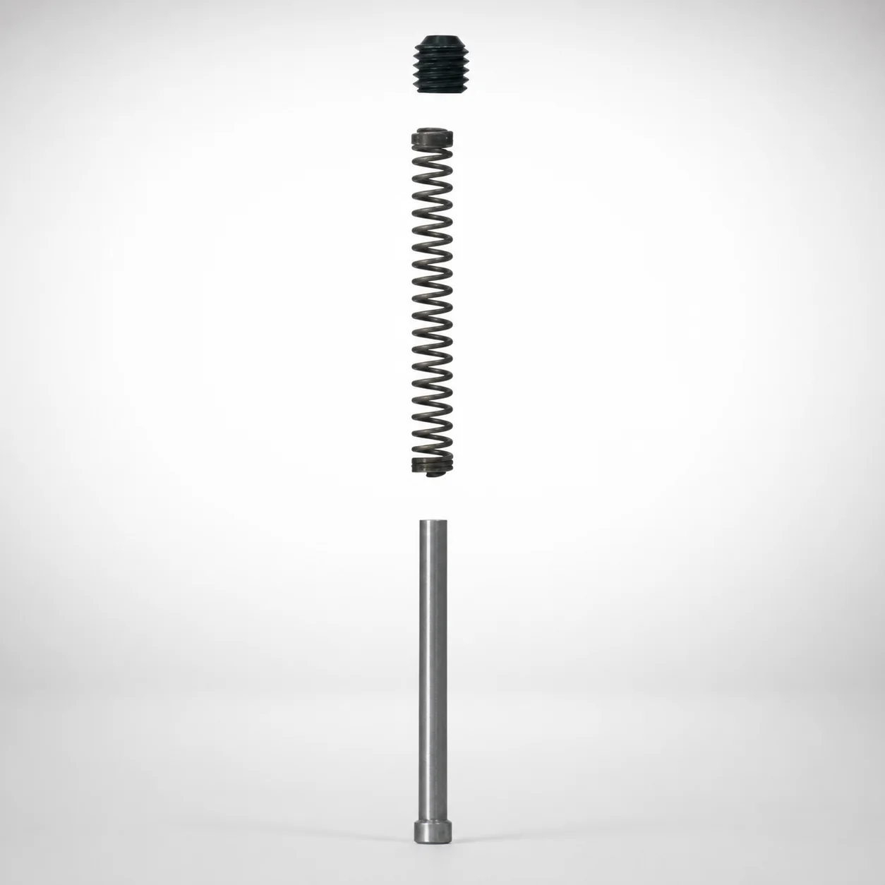
JIS Standard Ejector Pin Sets - Long Pins, Springs, Screw Plugs
Ejector Pin Sets - Long Pins, Springs, Screw Plugs deliver reliable precision alignment in mold assembly by keeping components consistently positioned. These sets are designed to improve mold performance and support long service life under high-demand production.
- Long-type ejector pin set layout improves repeatable component alignment
- Durable construction helps reduce wear and protect sensitive systems
- Supports stable assembly through controlled L dimension options
- Commonly used in injection molding to maintain consistent part quality
Specifications
12 configurations available
| L (L dimension) (mm) | FL (Spring length) (mm) | D (Applicable punch diameter) (mm) | Sales form (mm) | type |
|---|---|---|---|---|
| 41 ~ 81 | 30 ~ 60 | 5 | Set package | - |
| 41 ~ 81 | - | 5 | Pin only | - |
| 41 ~ 81 | 30 ~ 60 | 6 | Set package | - |
| 41 ~ 81 | - | 6 | Pin only | - |
| 41.5 ~ 101.5 | 30 ~ 60 | 8 | Set package | - |
| 41.5 ~ 101.5 | - | 8 | Pin only | - |
| 41.5 ~ 101.5 | 30 ~ 60 | 10 | Set package | - |
| 41.5 ~ 101.5 | - | 10 | Pin only | - |
| 41.5 ~ 101.5 | 30 ~ 60 | 13 | Set package | - |
| 41.5 ~ 101.5 | - | 13 | Pin only | - |
| 42 ~ 102 | 30 ~ 60 | 16/20/25 | Set package | - |
| 42 ~ 102 | - | 16/20/25 | Pin only | - |
Product Guide
Application Scenarios+
This long-pin ejector pin set is used in injection mold assemblies where consistent, repeatable positioning of ejector hardware is critical. It is well-suited for automotive and appliance component molds that run high cycle counts, because the set layout is designed to maintain stable alignment during ejector travel and reduce component-to-component misfit over time.
In electronics and connector housing molds, the long pin configuration helps preserve coaxiality between moving parts and ejector systems, supporting uniform ejection and reducing localized wear on surrounding guides.
For consumer and packaging parts that require reliable ejection under varying shot-to-shot conditions, the available L dimension range (41–81 mm, 41.5–101.5 mm, or 42–102 mm) allows engineers to match stroke/clearance requirements while keeping the spring travel controlled by the FL spring length (30–60 mm).
- Choose the variant that matches the required L and FL to keep ejection alignment stable
- Select by compatible punch diameter D (5, 6, 8, 10, 13, or 16/20/25) for fit into the molded tooling layout
Material & Process Details+
Material and heat-treatment details are not provided in the supplied specifications for this ejector pin set. Therefore, heat treatment state, HRC hardness, and steel grade equivalents (e.g., H13/H13-like or M2/M2-like) cannot be stated accurately for this specific variant.
To ensure correct wear resistance and toughness balance for your application, confirm the steel grade and hardening method from the product documentation or MISUMI catalog data for the corresponding configuration (pin-only versus set package) and the selected D (punch diameter) and L option.
- Verification needed: steel grade, target hardness (HRC), and whether pins are nitrided, quenched & tempered, or pre-hardened
- Engineering trade-off: higher hardness improves wear resistance but may reduce toughness if impact loading is significant
- Practical check: confirm guide fit and spring behavior for long-travel stability (controlled by FL = 30–60 mm)
Sizing & Selection Guide+
Correct selection starts with matching the ejector travel/stack-up to the L (length) dimension. Available options are 41–81 mm, 41.5–101.5 mm, or 42–102 mm. Choose the range that fits your mold’s moving plate-to-ejector interface and required clearance through the full operating stroke.
Next, match the spring configuration using FL (spring length) = 30–60 mm. The selected FL should provide the needed spring working height so that compression remains within design limits and maintains stable force during ejection.
Finally, verify compatibility with the tooling geometry by selecting the applicable punch diameter D: 5, 6, 8, 10, 13, or 16/20/25 mm. This D must align with the mating punch/ejector bore sizing in your mold.
- Fit & tolerance: confirm your machine shop’s tolerance strategy for pin-to-bore clearance after selecting D
- Configurable vs fixed: L and FL are selected by configuration ranges; D is the diameter variant; package form is either set package or pin only
Frequently Asked Questions
Which L dimension range should I choose for a long-travel ejector stack?+
How do I select the correct spring length FL for stable ejection force?+
What punch diameter D options are compatible with this ejector pin set?+
Should I order the set package or pin only for my existing tooling?+
How do L and D jointly affect alignment in multi-cavity or long-core molds?+
Related Products
Need Custom Specifications?
Our engineering team can help with custom configurations, material selection, and volume pricing.