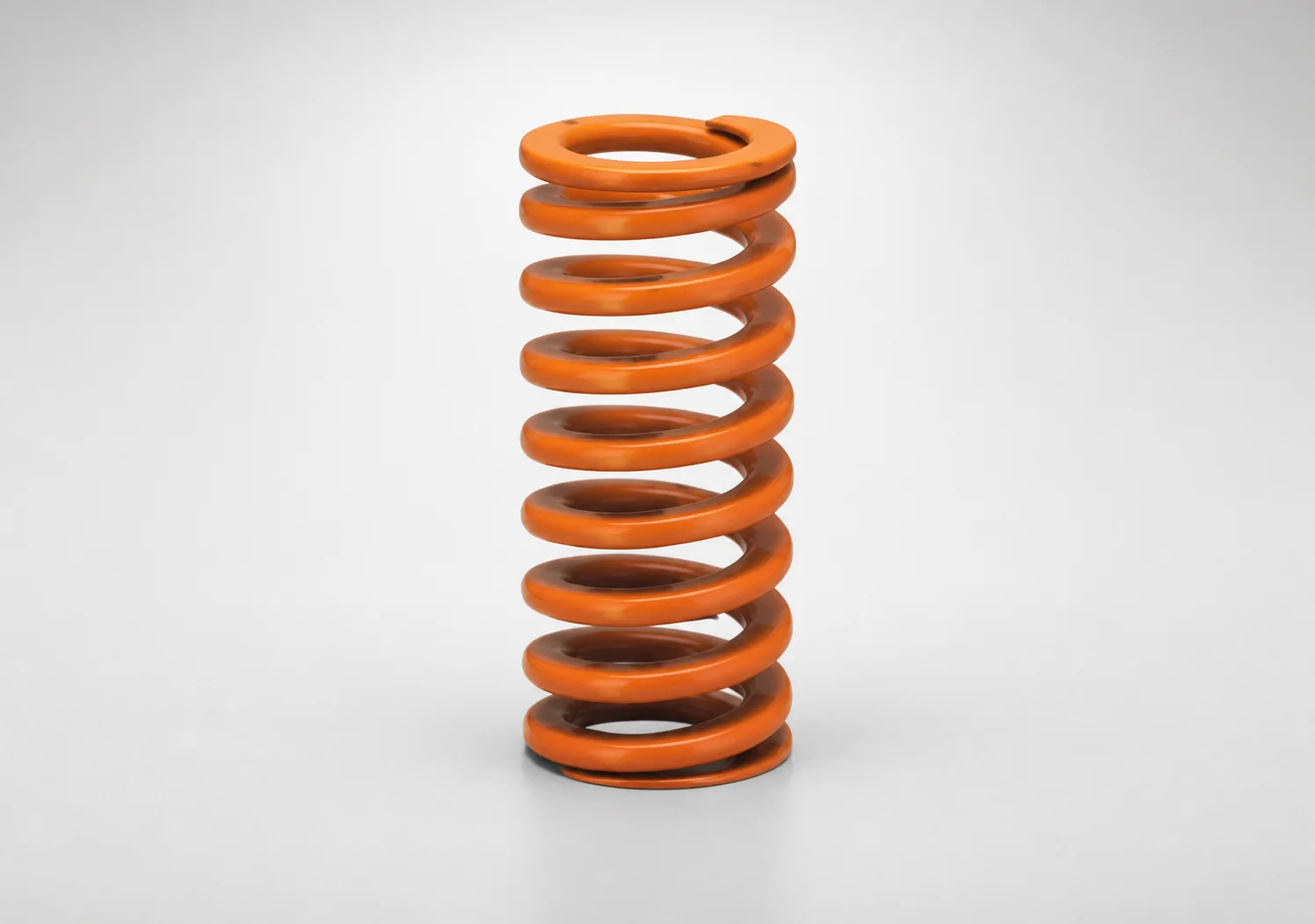
SWS Series Medium Deflection Coil Springs (40% Deflection) - Flat Wire
Medium deflection coil spring (40% deflection) (SWS series) uses flat wire to deliver reliable force response in compact spring applications where controlled deflection matters. Built for heat resistance up to 200°C for consistent performance.
- 40% medium deflection design supports predictable load under compression cycles
- Flat wire construction improves spring packaging and consistent force behavior
- Heat resistant to 200°C for stable operation in thermally stressed equipment
- Available with or without paint peeling to match assembly and handling requirements
Specifications
414 configurations available
| D (Diameter) (mm) | L (Length) (mm) | d (Inner Diameter - Flat Type Only) | Spring Constant (N/mm) | Load (N) | Allowable Deflection (mm) | With/without paint peeling | type |
|---|---|---|---|---|---|---|---|
| 10.5 | 20 | 5.5 | 10.90 | 87.2 | 8 | Yes | - |
| 10.5 | 25 | 5.5 | 8.72 | 87.2 | 10 | Yes | - |
| 10.5 | 30 | 5.5 | 7.27 | 87.2 | 12 | Yes | - |
| 10.5 | 35 | 5.5 | 6.23 | 87.2 | 14 | Yes | - |
| 10.5 | 40 | 5.5 | 5.45 | 87.2 | 16 | Yes | - |
| 10.5 | 45 | 5.5 | 4.84 | 87.2 | 18 | Yes | - |
| 10.5 | 50 | 5.5 | 4.36 | 87.2 | 20 | Yes | - |
| 10.5 | 55 | 5.5 | 3.96 | 87.2 | 22 | Yes | - |
| 10.5 | 60 | 5.5 | 3.63 | 87.2 | 24 | Yes | - |
| 10.5 | 65 | 5.5 | 3.35 | 87.2 | 26 | Yes | - |
| 10.5 | 70 | 5.5 | 3.11 | 87.2 | 28 | Yes | - |
| 10.5 | 75 | 5.5 | 2.91 | 87.2 | 30 | Yes | - |
| 10.5 | 80 | 5.5 | 2.73 | 87.2 | 32 | Yes | - |
| 12.5 | 20 | 6.5 | 15.25 | 122.0 | 8 | Yes | - |
| 12.5 | 25 | 6.5 | 12.20 | 122.0 | 10 | Yes | - |
| 12.5 | 30 | 6.5 | 10.17 | 122.0 | 12 | Yes | - |
| 12.5 | 35 | 6.5 | 8.71 | 122.0 | 14 | Yes | - |
| 12.5 | 40 | 6.5 | 7.63 | 122.0 | 16 | Yes | - |
| 12.5 | 45 | 6.5 | 6.78 | 122.0 | 18 | Yes | - |
| 12.5 | 50 | 6.5 | 6.10 | 122.0 | 20 | Yes | - |
| 12.5 | 55 | 6.5 | 5.55 | 122.0 | 22 | Yes | - |
| 12.5 | 60 | 6.5 | 5.08 | 122.0 | 24 | Yes | - |
| 12.5 | 65 | 6.5 | 4.69 | 122.0 | 26 | Yes | - |
| 12.5 | 70 | 6.5 | 4.36 | 122.0 | 28 | Yes | - |
| 12.5 | 75 | 6.5 | 4.07 | 122.0 | 30 | Yes | - |
| 12.5 | 80 | 6.5 | 3.81 | 122.0 | 32 | Yes | - |
| 14.5 | 20 | 8.5 | 24.50 | 196.0 | 8 | Yes | - |
| 14.5 | 25 | 8.5 | 19.61 | 196.0 | 10 | Yes | - |
| 14.5 | 30 | 8.5 | 16.33 | 196.0 | 12 | Yes | - |
| 14.5 | 35 | 8.5 | 14.00 | 196.0 | 14 | Yes | - |
| 14.5 | 40 | 8.5 | 12.25 | 196.0 | 16 | Yes | - |
| 14.5 | 45 | 8.5 | 10.89 | 196.0 | 18 | Yes | - |
| 14.5 | 50 | 8.5 | 9.8 | 196.0 | 20 | Yes | - |
| 14.5 | 55 | 8.5 | 8.91 | 196.0 | 22 | Yes | - |
| 14.5 | 60 | 8.5 | 8.17 | 196.0 | 24 | Yes | - |
| 14.5 | 65 | 8.5 | 7.54 | 196.0 | 26 | Yes | - |
| 14.5 | 70 | 8.5 | 7 | 196.0 | 28 | Yes | - |
| 14.5 | 75 | 8.5 | 6.53 | 196.0 | 30 | Yes | - |
| 14.5 | 80 | 8.5 | 6.13 | 196.0 | 32 | Yes | - |
| 14.5 | 90 | 8.5 | 5.44 | 196.0 | 36 | Yes | - |
| 14.5 | 100 | 8.5 | 4.9 | 196.0 | 40 | Yes | - |
| 14.5 | 125 | 8.5 | 3.92 | 196.0 | 50 | Yes | - |
| 14.5 | 150 | 8.5 | 3.27 | 196.0 | 60 | Yes | - |
| 17 | 25 | 10.5 | 29.42 | 294.2 | 10 | Yes | - |
| 17 | 30 | 10.5 | 24.52 | 294.2 | 12 | Yes | - |
| 17 | 35 | 10.5 | 21.01 | 294.2 | 14 | Yes | - |
| 17 | 40 | 10.5 | 18.39 | 294.2 | 16 | Yes | - |
| 17 | 45 | 10.5 | 16.34 | 294.2 | 18 | Yes | - |
| 17 | 50 | 10.5 | 14.71 | 294.2 | 20 | Yes | - |
| 17 | 55 | 10.5 | 13.37 | 294.2 | 22 | Yes | - |
Product Guide
Application Scenarios+
These medium-deflection coil springs are used in injection mold accessory systems where a compact spring element must deliver stable force over repeated compression. A typical scenario is automotive connector and sensor housing molds, where guides, ejector-related mechanisms, or retention hardware require predictable load response as temperature and cycle rates increase.
In consumer electronics enclosures and small-part tooling, flat-wire construction helps improve packaging density and maintains more consistent spring behavior under limited installation space.
They are also suited for thermally stressed processing setups that see elevated ambient/tool temperatures, because this variant supports operation up to 200°C. Engineers commonly select the 40% deflection design when the mold assembly needs controlled travel (“allowable deflection”) and repeatable force for reliable actuation and part release support.
- 40% medium deflection supports predictable load vs. compression cycles
- Flat wire improves stability and consistent force behavior in tight layouts
- Heat resistance to 200°C helps maintain performance under thermal loads
Material & Process Details+
The provided data for this SWS medium-deflection spring focuses on performance and heat resistance rather than a specific steel grade (e.g., SKD61/H13 or SKH51/M2). Therefore, material microstructure, exact hardness (HRC), and heat-treatment state (quench & temper, nitriding, etc.) cannot be stated from the current specification set.
What can be confirmed is the functional requirement: stable force behavior with heat resistance up to 200°C, which is typically associated with spring steels and protective finishing appropriate for tool environments. The flat wire form factor is a manufacturing-oriented choice that helps achieve controlled deflection and consistent load response in compact installations.
- Hardness (HRC): not specified in the supplied metadata
- Heat treatment: not specified in the supplied metadata
- Trade-offs: without grade and temper data, wear resistance vs. toughness cannot be quantified
If you share the exact spring steel grade and drawing tolerance notes for this series, we can document hardness, wear resistance expectations, and the corresponding heat-treatment route accurately.
Sizing & Selection Guide+
Correct sizing starts by matching the spring’s D (10.5 ~ 52 mm) and L (20 ~ 300 mm) to the available envelope in your mold cavity/core support area. The inner diameter d is configurable for flat-wire type only and ranges from 5.5 ~ 37 mm, so verify clearance around shafts/bolts and any guide features before final selection.
Next, ensure force and travel requirements align with the spring’s working range. Use the specified allowable deflection (8 ~ 120 mm) to set the target compression during operation, and confirm the required spring constant (2.73 ~ 1307 N/mm) and load (87.2 ~ 1570 N) at your planned deflection.
- Envelope match: choose D and L within 10.5–52 mm and 20–300 mm
- Clearance match: choose d within 5.5–37 mm (flat type)
- Performance match: verify allowable deflection and load at the working compression
Finish option with/without paint peeling is selectable (Yes/No) to match assembly handling and adjacent components requirements; dimensional tolerances are not provided in the supplied spec set, so use your drawing and supplier datasheet for fit-critical interfaces.
Frequently Asked Questions
How do I select the allowable deflection (8–120 mm) so the spring stays within the intended 40% medium-deflection range?+
What dimensions should I verify first when space is limited around a guide shaft or ejector pin?+
Can this spring be used in tooling that reaches elevated temperatures, and how does the 200°C rating affect selection?+
What is the difference between choosing 'with paint peeling' versus 'without paint peeling' for mold assembly integration?+
How do I ensure the spring constant and load (2.73–1307 N/mm, 87.2–1570 N) match my mechanism’s force requirement?+
Related Products
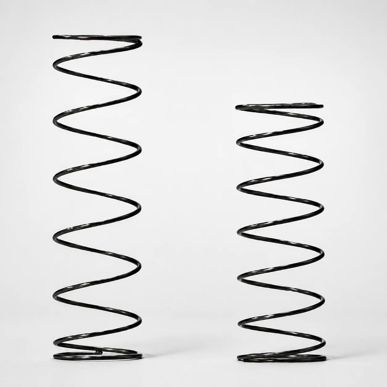
Heat Resistant Round Wire Spring - 60% Deflection (WFH Series)
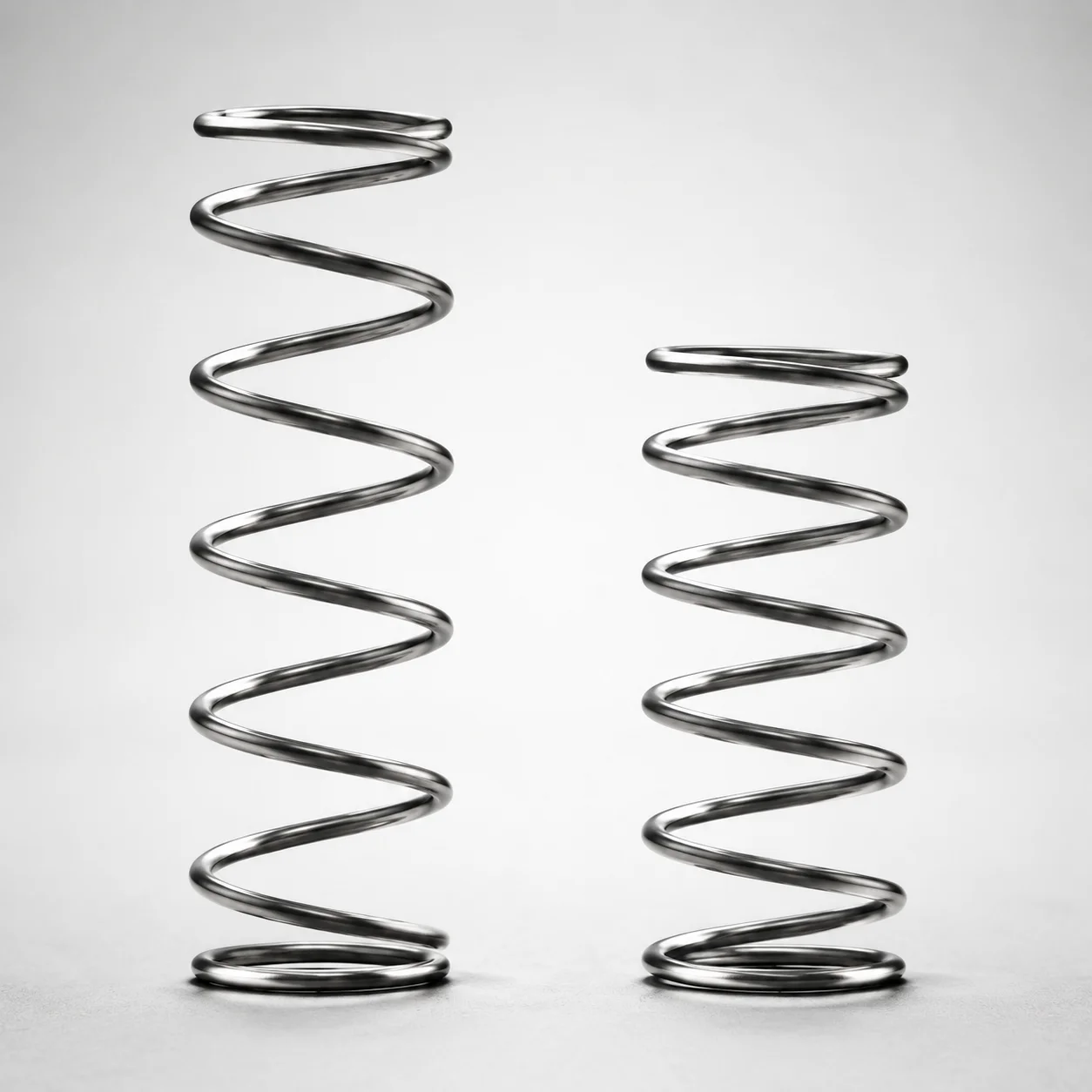
WLH Series Heat Resistant Round Wire Spring - 50% Deflection
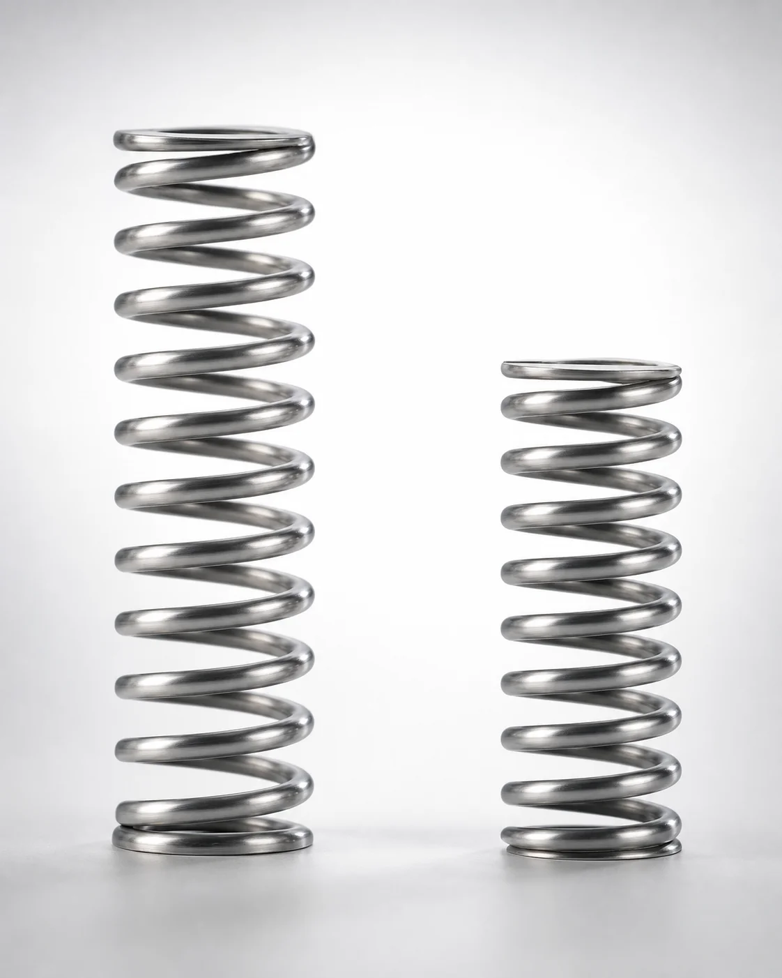
WHH Series 35% Deflection Heat Resistant Coil Spring
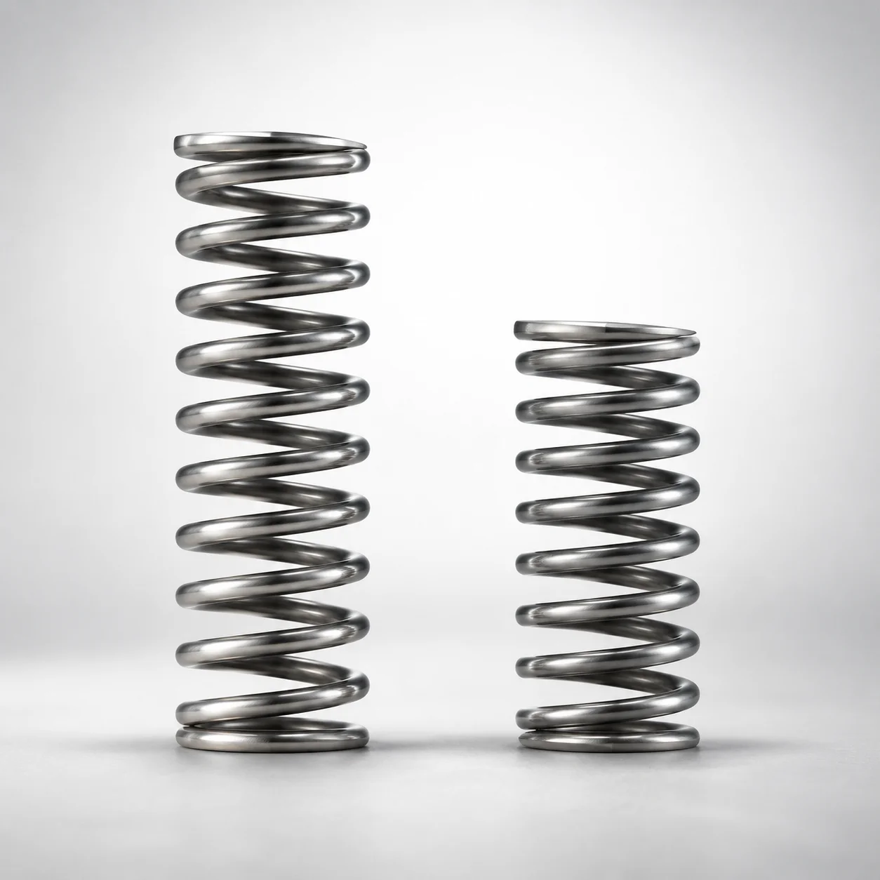
Heat Resistant Round Wire Spring 40% Deflection (WMH Series)
Super-High Deflection Coil Spring - 60% Deflection
Ultra-High Deflection Coil Springs - 65% Deflection SWY Series
Need Custom Specifications?
Our engineering team can help with custom configurations, material selection, and volume pricing.