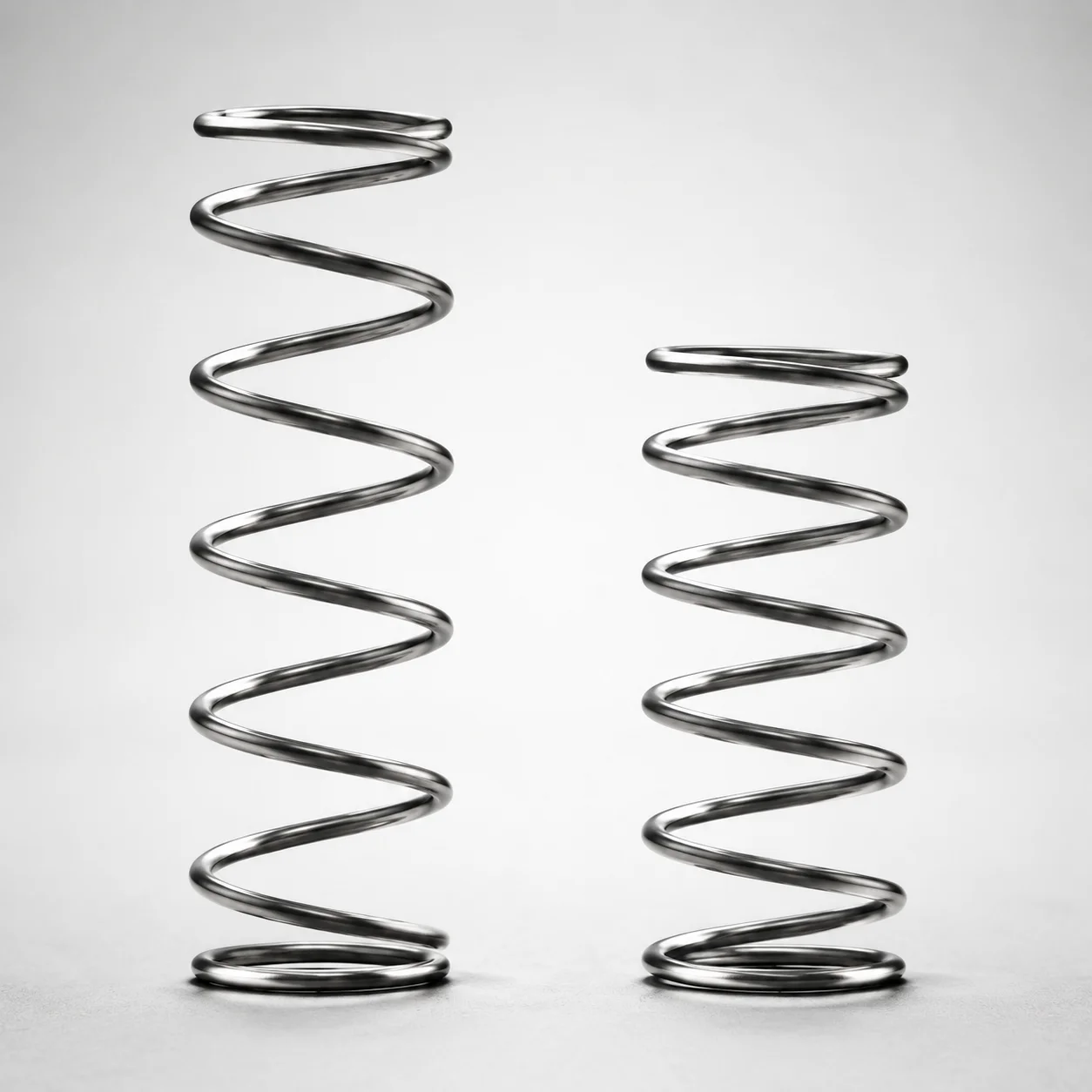
WLH Series Heat Resistant Round Wire Spring - 50% Deflection
WLH Series Heat Resistant Round Wire Spring - 50% Deflection delivers stable load response for high-temperature applications, rated up to 200°C. It is engineered as a round wire coil spring to maintain performance under heat and cycling.
- Round wire coil spring design for consistent 50% deflection behavior
- Heat resistance rated to 200°C for reliable operation in hot tooling
- WLH spring type configuration supports predictable spring characteristics
- Suitable for molds, fixtures, and mechanisms requiring thermally stable spring return
Specifications
103 configurations available
| D (Diameter) (mm) | L (Length) (mm) | Spring Constant (N/mm) | Load (N) | Allowable Deflection (mm) | type |
|---|---|---|---|---|---|
| 4 | 5 | 1.0 | 2.5 | 2.5 | - |
| 4 | 10 | 1.0 | 4.9 | 5 | - |
| 4 | 15 | 1.0 | 7.4 | 7.5 | - |
| 4 | 20 | 1.0 | 9.8 | 10 | - |
| 4 | 25 | 1.0 | 12.3 | 12.5 | - |
| 4 | 30 | 1.0 | 14.7 | 15 | - |
| 4 | 35 | 1.0 | 17.2 | 17.5 | - |
| 4 | 40 | 1.0 | 19.6 | 20 | - |
| 5 | 5 | 1.0 | 2.5 | 2.5 | - |
| 5 | 10 | 1.0 | 4.9 | 5 | - |
| 5 | 15 | 1.0 | 7.4 | 7.5 | - |
| 5 | 20 | 1.0 | 9.8 | 10 | - |
| 5 | 25 | 1.0 | 12.3 | 12.5 | - |
| 5 | 30 | 1.0 | 14.7 | 15 | - |
| 5 | 35 | 1.0 | 17.2 | 17.5 | - |
| 5 | 40 | 1.0 | 19.6 | 20 | - |
| 5 | 45 | 1.0 | 22.1 | 22.5 | - |
| 5 | 50 | 1.0 | 24.5 | 25 | - |
| 6 | 5 | 1.0 | 2.9 | 2.5 | - |
| 6 | 10 | 1.0 | 4.9 | 5 | - |
| 6 | 15 | 1.0 | 7.8 | 7.5 | - |
| 6 | 20 | 1.0 | 9.8 | 10 | - |
| 6 | 25 | 1.0 | 12.7 | 12.5 | - |
| 6 | 30 | 1.0 | 14.7 | 15 | - |
| 6 | 35 | 1.0 | 17.7 | 17.5 | - |
| 6 | 40 | 1.0 | 19.6 | 20 | - |
| 6 | 45 | 1.0 | 22.6 | 22.5 | - |
| 6 | 50 | 1.0 | 24.5 | 25 | - |
| 6 | 55 | 1.0 | 27.0 | 27.5 | - |
| 6 | 60 | 1.0 | 29.4 | 30 | - |
| 6 | 65 | 1.0 | 31.9 | 32.5 | - |
| 6 | 70 | 1.0 | 34.3 | 35 | - |
| 6 | 80 | 1.0 | 39.2 | 40 | - |
| 8 | 10 | 1.0 | 4.9 | 5 | - |
| 8 | 15 | 1.0 | 7.8 | 7.5 | - |
| 8 | 20 | 1.0 | 9.8 | 10 | - |
| 8 | 25 | 1.0 | 12.7 | 12.5 | - |
| 8 | 30 | 1.0 | 14.7 | 15 | - |
| 8 | 35 | 1.0 | 17.7 | 17.5 | - |
| 8 | 40 | 1.0 | 19.6 | 20 | - |
| 8 | 45 | 1.0 | 22.6 | 22.5 | - |
| 8 | 50 | 1.0 | 24.5 | 25 | - |
| 8 | 55 | 1.0 | 27.0 | 27.5 | - |
| 8 | 60 | 1.0 | 29.4 | 30 | - |
| 8 | 65 | 1.0 | 31.9 | 32.5 | - |
| 8 | 70 | 1.0 | 34.3 | 35 | - |
| 8 | 80 | 1.0 | 39.2 | 40 | - |
| 10 | 10 | 1.0 | 4.9 | 5 | - |
| 10 | 15 | 1.0 | 7.8 | 7.5 | - |
| 10 | 20 | 1.0 | 9.8 | 10 | - |
Product Guide
Application Scenarios+
This heat-resistant round wire coil spring is used as a mold accessory in injection tooling where a stable return force is needed despite elevated temperatures. Because it is rated for continuous service up to 200°C, it helps maintain consistent actuation and part ejection timing in hot-runner and hot-gate environments.
- Automotive and appliance connector molds: replaceable springs in slides or small retract mechanisms to preserve repeatable clamp/eject loads while cycling under elevated tooling temperatures.
- Packaging and consumer electronics housings: thermally stable spring return for lifters or mechanisms that must recover position after high-heat molding cycles.
- Fixturing and secondary operations: use as a heat-tolerant spring element in fixtures that require predictable 50% deflection load behavior.
The round-wire coil geometry and defined 50% deflection characteristic make it suitable for designs that require predictable spring response rather than overspecified force for the full stroke.
Material & Process Details+
The WLH series is specified as a heat resistant round wire coil spring intended for continuous service up to 200°C. Within the provided product data, the exact steel grade and heat-treatment recipe (e.g., quench & temper, nitriding) are not specified, so material hardness values and microstructural conditions cannot be stated from the current specifications.
- Heat resistance focus: designed to maintain spring performance during thermal cycling at up to 200°C.
- Wear/handling trade-off: coil springs prioritize elasticity and fatigue life; overly aggressive hardening that maximizes surface wear resistance can reduce toughness and shift stress distribution.
- Process fit: selection is typically based on required load and allowable deflection rather than material-hardness targets, when only WLH temperature capability is known.
If you need a specific steel grade, hardness (HRC), or heat-treatment state, share your preferred tolerance/fatigue requirements so we can align the spring specification accordingly.
Sizing & Selection Guide+
Choose the spring by matching required force, stroke, and geometry from the provided ranges. The WLH series is specified around a 50% deflection behavior, so allowable deflection and resulting load should be checked at the deflection point used by your mechanism.
- Wire diameter (D): select within 4 ~ 18 mm based on space constraints and desired stiffness.
- Spring length (L): select within 5 ~ 100 mm to fit the installed height and to avoid coil bind.
- Allowable deflection: ensure your stroke does not exceed 2.5 ~ 50 mm allowable deflection for the selected size.
- Load requirement: match the expected load in N using the provided ranges 2.5 ~ 147.1 N and the spring constant options (1.0 or 2.9 N/mm).
Fit considerations: confirm installed free length versus compressed/extended length so the spring operates within allowable deflection; since no explicit tolerance band is given, verify fit using your mechanism’s clearance and the target deflection point.
Frequently Asked Questions
Which spring size should I select when my mechanism stroke is within 2.5 to 50 mm?+
How does the 50% deflection rating affect load prediction for WLH springs?+
Can WLH springs be used for hot tooling at temperatures above typical molding cycles?+
What is the correct way to choose between spring constant 1.0 N/mm and 2.9 N/mm?+
What dimensions should I confirm to avoid coil bind and ensure proper installation?+
Related Products
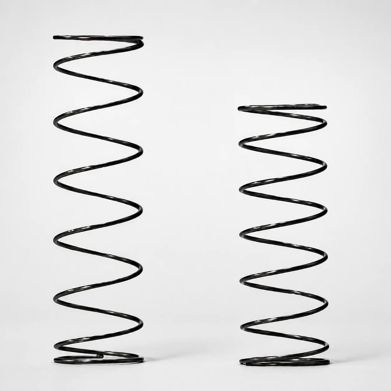
Heat Resistant Round Wire Spring - 60% Deflection (WFH Series)
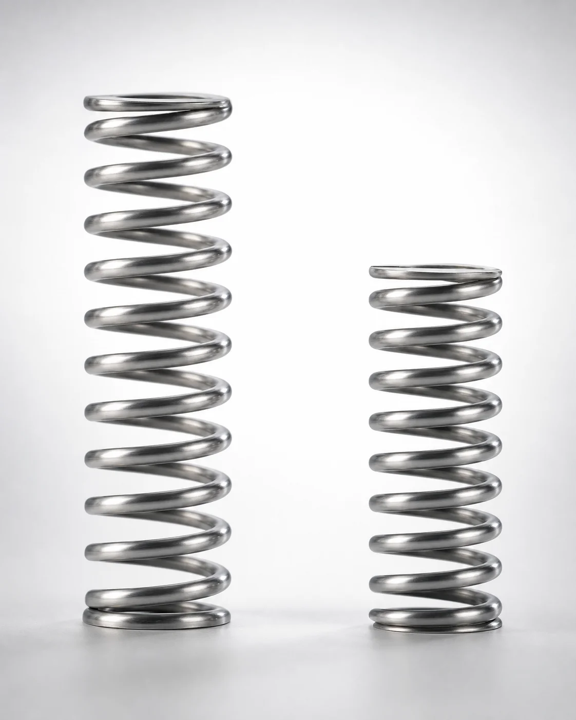
WHH Series 35% Deflection Heat Resistant Coil Spring
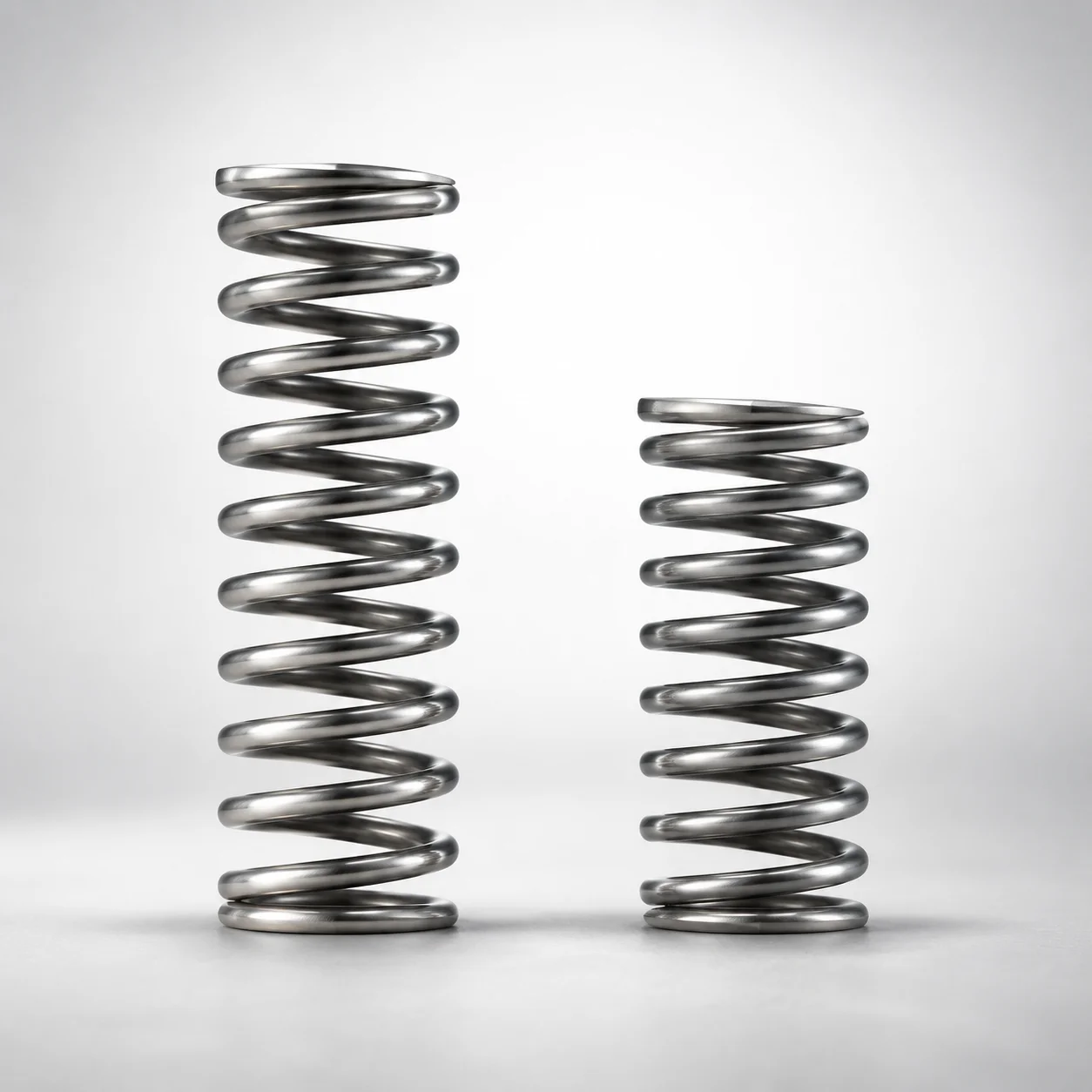
Heat Resistant Round Wire Spring 40% Deflection (WMH Series)
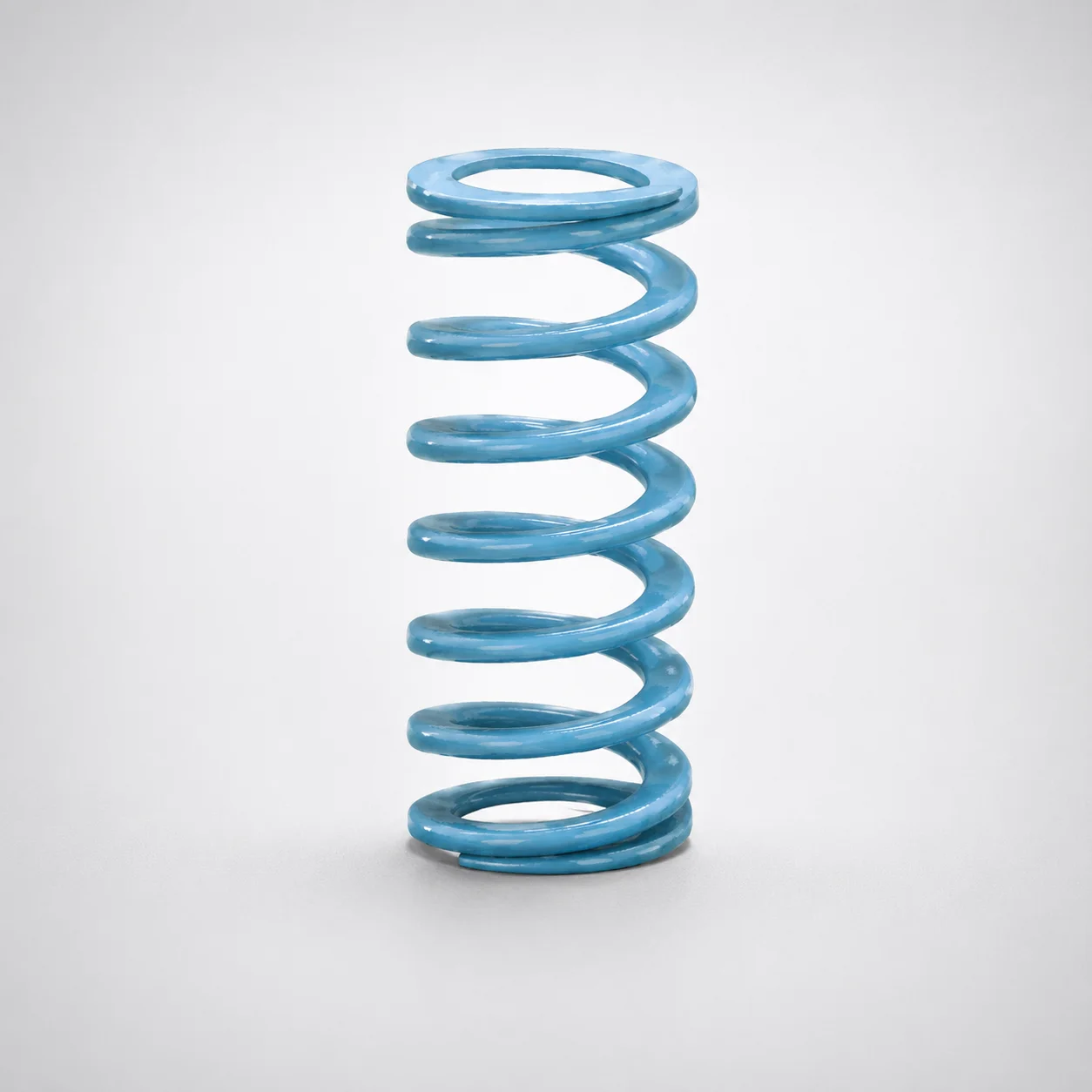
Super-High Deflection Coil Spring - 60% Deflection
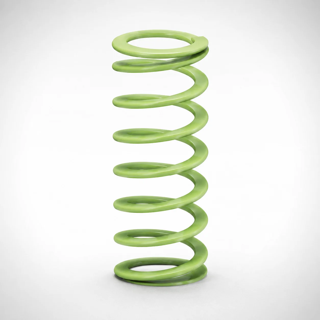
Ultra-High Deflection Coil Springs - 65% Deflection SWY Series
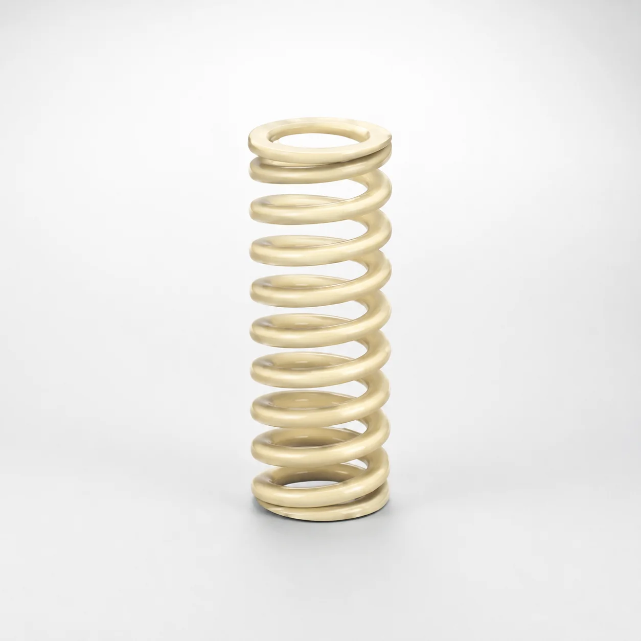
High Deflection Coil Springs (50% Deflection) SWR Series
Need Custom Specifications?
Our engineering team can help with custom configurations, material selection, and volume pricing.