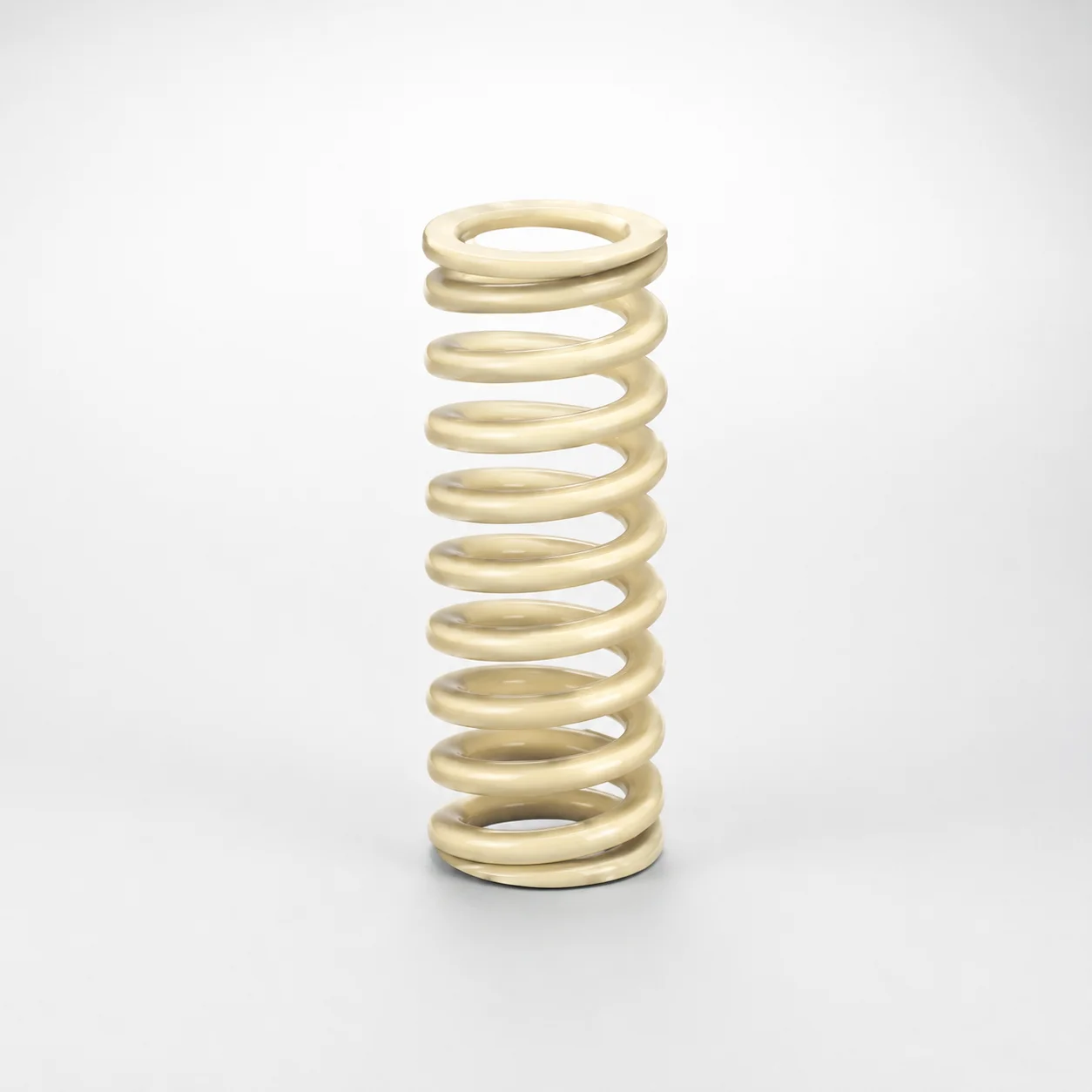
High Deflection Coil Springs (50% Deflection) SWR Series
High Deflection Coil Springs (50% Deflection) SWR Series are engineered for stable force delivery under larger deflection, using a flat wire construction. With 200°C heat resistance, these springs help maintain performance in demanding production environments.
- Optimized for 50% deflection to support controlled load during stroke
- Flat wire design provides reliable spring geometry and consistent force characteristics
- Heat resistant construction for operation up to 200°C in hot-process conditions
- Commonly used in mechanisms requiring predictable compliance and repeatable loading
Specifications
442 configurations available
| D (Diameter) (mm) | L (Length) (mm) | d (Inner Diameter - Flat Type Only) | Spring Constant (N/mm) | Load (N) | Allowable Deflection (mm) | With/without paint peeling | type |
|---|---|---|---|---|---|---|---|
| 10.5 | 15 | 6.0 | 10.46 | 78.5 | 7.5 | Yes | - |
| 10.5 | 20 | 6.0 | 7.85 | 78.5 | 10 | Yes | - |
| 10.5 | 25 | 6.0 | 6.28 | 78.5 | 12.5 | Yes | - |
| 10.5 | 30 | 6.0 | 5.23 | 78.5 | 15 | Yes | - |
| 10.5 | 35 | 6.0 | 4.48 | 78.5 | 17.5 | Yes | - |
| 10.5 | 40 | 6.0 | 3.92 | 78.5 | 20 | Yes | - |
| 10.5 | 45 | 6.0 | 3.49 | 78.5 | 22.5 | Yes | - |
| 10.5 | 50 | 6.0 | 3.14 | 78.5 | 25 | Yes | - |
| 10.5 | 55 | 6.0 | 2.85 | 78.5 | 27.5 | Yes | - |
| 10.5 | 60 | 6.0 | 2.62 | 78.5 | 30 | Yes | - |
| 10.5 | 65 | 6.0 | 2.41 | 78.5 | 32.5 | Yes | - |
| 10.5 | 70 | 6.0 | 2.24 | 78.5 | 35 | Yes | - |
| 10.5 | 75 | 6.0 | 2.09 | 78.5 | 37.5 | Yes | - |
| 10.5 | 80 | 6.0 | 1.96 | 78.5 | 40 | Yes | - |
| 12.5 | 15 | 7 | 11.77 | 88.3 | 7.5 | Yes | - |
| 12.5 | 20 | 7 | 8.83 | 88.3 | 10 | Yes | - |
| 12.5 | 25 | 7 | 7.06 | 88.3 | 12.5 | Yes | - |
| 12.5 | 30 | 7 | 5.88 | 88.3 | 15 | Yes | - |
| 12.5 | 35 | 7 | 5.04 | 88.3 | 17.5 | Yes | - |
| 12.5 | 40 | 7 | 4.41 | 88.3 | 20 | Yes | - |
| 12.5 | 45 | 7 | 3.92 | 88.3 | 22.5 | Yes | - |
| 12.5 | 50 | 7 | 3.53 | 88.3 | 25 | Yes | - |
| 12.5 | 55 | 7 | 3.21 | 88.3 | 27.5 | Yes | - |
| 12.5 | 60 | 7 | 2.94 | 88.3 | 30 | Yes | - |
| 12.5 | 65 | 7 | 2.72 | 88.3 | 32.5 | Yes | - |
| 12.5 | 70 | 7 | 2.52 | 88.3 | 35 | Yes | - |
| 12.5 | 75 | 7 | 2.35 | 88.3 | 37.5 | Yes | - |
| 12.5 | 80 | 7 | 2.21 | 88.3 | 40 | Yes | - |
| 12.5 | 90 | 7 | 1.96 | 88.3 | 45 | Yes | - |
| 12.5 | 100 | 7 | 1.77 | 88.3 | 50 | Yes | - |
| 14.5 | 15 | 8.5 | 17.00 | 127.5 | 7.5 | Yes | - |
| 14.5 | 20 | 8.5 | 12.75 | 127.5 | 10 | Yes | - |
| 14.5 | 25 | 8.5 | 10.20 | 127.5 | 12.5 | Yes | - |
| 14.5 | 30 | 8.5 | 8.50 | 127.5 | 15 | Yes | - |
| 14.5 | 35 | 8.5 | 7.28 | 127.5 | 17.5 | Yes | - |
| 14.5 | 40 | 8.5 | 6.37 | 127.5 | 20 | Yes | - |
| 14.5 | 45 | 8.5 | 5.67 | 127.5 | 22.5 | Yes | - |
| 14.5 | 50 | 8.5 | 5.10 | 127.5 | 25 | Yes | - |
| 14.5 | 55 | 8.5 | 4.64 | 127.5 | 27.5 | Yes | - |
| 14.5 | 60 | 8.5 | 4.25 | 127.5 | 30 | Yes | - |
| 14.5 | 65 | 8.5 | 3.92 | 127.5 | 32.5 | Yes | - |
| 14.5 | 70 | 8.5 | 3.64 | 127.5 | 35 | Yes | - |
| 14.5 | 75 | 8.5 | 3.40 | 127.5 | 37.5 | Yes | - |
| 14.5 | 80 | 8.5 | 3.19 | 127.5 | 40 | Yes | - |
| 14.5 | 90 | 8.5 | 2.83 | 127.5 | 45 | Yes | - |
| 14.5 | 100 | 8.5 | 2.55 | 127.5 | 50 | Yes | - |
| 14.5 | 125 | 8.5 | 2.04 | 127.5 | 62.5 | Yes | - |
| 14.5 | 150 | 8.5 | 1.70 | 127.5 | 75.0 | Yes | - |
| 17 | 20 | 10.5 | 19.61 | 196.1 | 10 | Yes | - |
| 17 | 25 | 10.5 | 15.69 | 196.1 | 12.5 | Yes | - |
Product Guide
Application Scenarios+
This high-deflection coil spring is used inside injection mold mechanisms where designers need stable compliance while the spring works deep into stroke. Its 50% deflection target helps maintain more predictable force as the moving components travel, reducing variability during cycling.
- Automotive connector and terminal molds: In hot-runner or high-cycle runner systems, the flat-wire geometry supports consistent return force for ejector-actuated compliance parts, especially where temperatures approach 200°C.
- Packaging and appliance housing molds: The spring’s controlled allowable deflection (7.5–200 mm) suits load-support requirements in large cavity structures, helping compensate for deflection-related tolerance stack-up.
- Medical device enclosure tooling: For mechanisms needing repeatable loading under deflection, the design supports reliable force delivery across varying cycle conditions.
Choose the flat-wire variant because it is intended to deliver repeatable force characteristics under significant deflection while sustaining performance up to 200°C.
Material & Process Details+
For this product variant, the provided specification confirms 200°C heat resistance, making it suitable for mold accessories exposed to hot-process conditions. The flat wire design is a key manufacturing feature that influences spring stiffness consistency and helps maintain spring geometry under repeated loading.
- Heat resistance: Rated for operation up to 200°C, helping preserve performance during elevated-temperature molding cycles.
- Material/heat treatment: The input data does not specify the exact steel grade, hardness (HRC), or heat treatment state (e.g., quenched & tempered, nitrided). Therefore, material microstructure and hardness trade-offs cannot be stated from the available parameters.
- Manufacturing process relevance: Flat-wire coil construction improves uniformity of the spring’s cross-section response, supporting stable spring constant across the intended deflection range.
If you need hardness or grade verification for critical wear or fatigue requirements, please request the material certificate for the specific size range.
Sizing & Selection Guide+
Start sizing by matching the spring’s allowable deflection and required load at the target stroke position. The product supports 7.5–200 mm of allowable deflection, with a spring constant range of 1.7–52.96 N/mm, which directly determines force response.
- Diameter (D): Select D = 10.5–50 mm to fit the surrounding guide space around the mold mechanism.
- Length (L): Choose L = 15–400 mm based on available axial room and desired coil working height.
- Inner diameter (d): For the flat type only, pick d = 6–36 mm to clear the shaft/rod and maintain alignment.
- Load target: Confirm the expected load of 78.5–1324 N at your working deflection; ensure your operating point stays within the allowable deflection band.
Tolerance/fit guidance is not provided in the input data; however, for flat-wire springs, alignment against the shaft (using d) is critical to avoid side loading and force variation. Paint finish can be selected via the with/without paint peeling option.
Frequently Asked Questions
How do I select the correct spring constant (N/mm) and allowable deflection for my mold stroke?+
What size constraints should I check first: D, L, or the flat inner diameter d?+
Is this spring suitable for hot-process areas approaching 200°C?+
Does the paint peeling option affect performance, and when should I choose with/without paint peeling?+
What does the 50% deflection rating mean for real-world load support in molds?+
Related Products
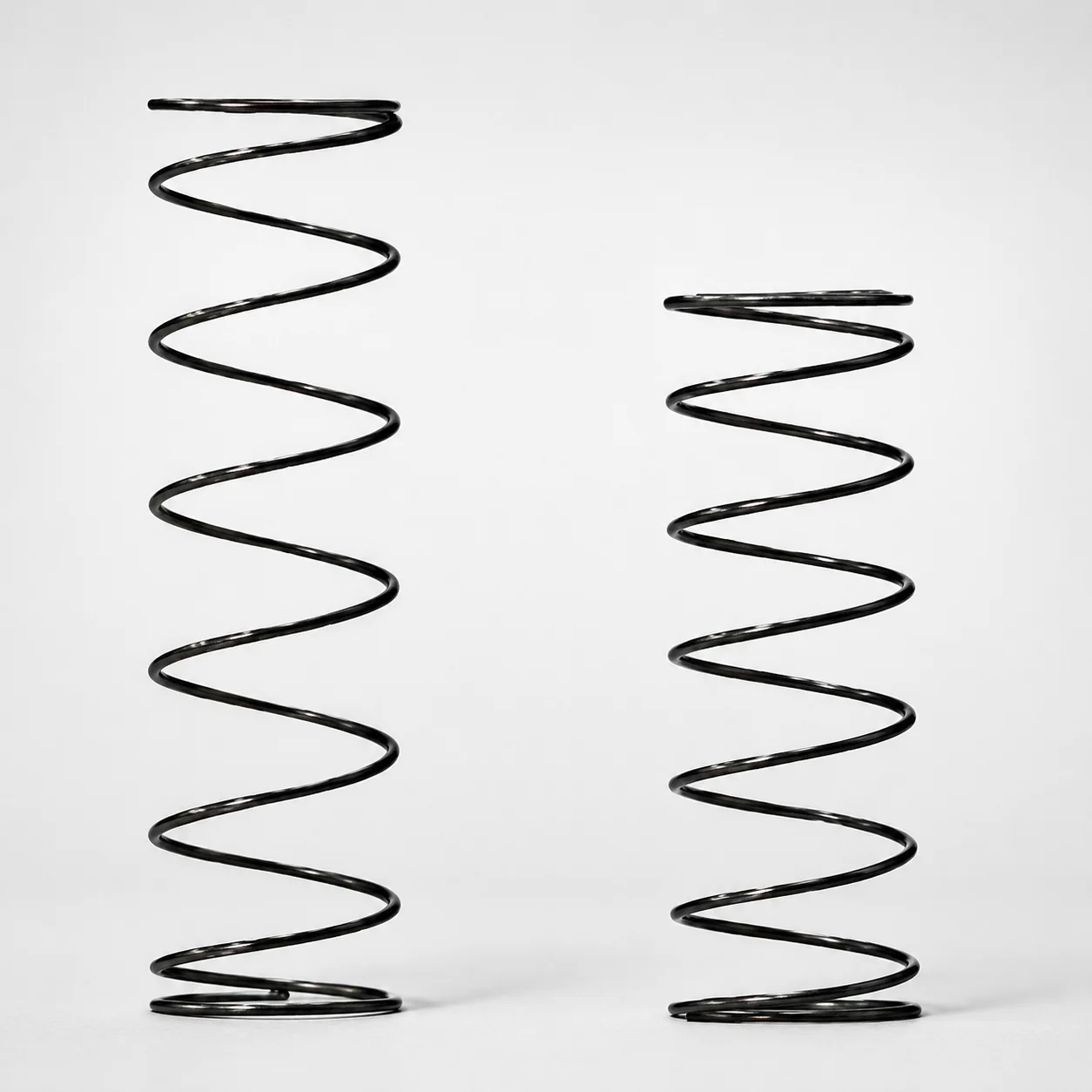
Heat Resistant Round Wire Spring - 60% Deflection (WFH Series)
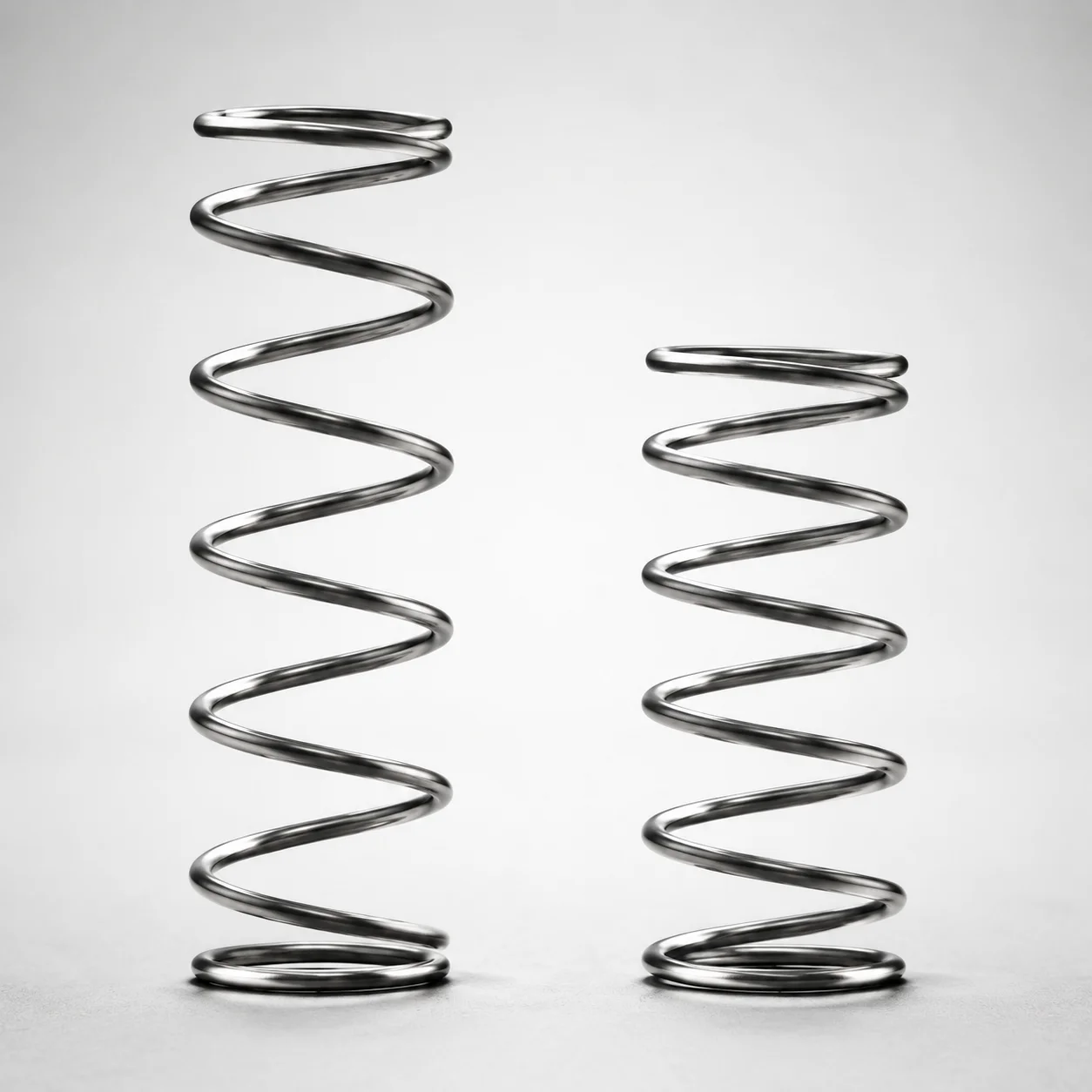
WLH Series Heat Resistant Round Wire Spring - 50% Deflection
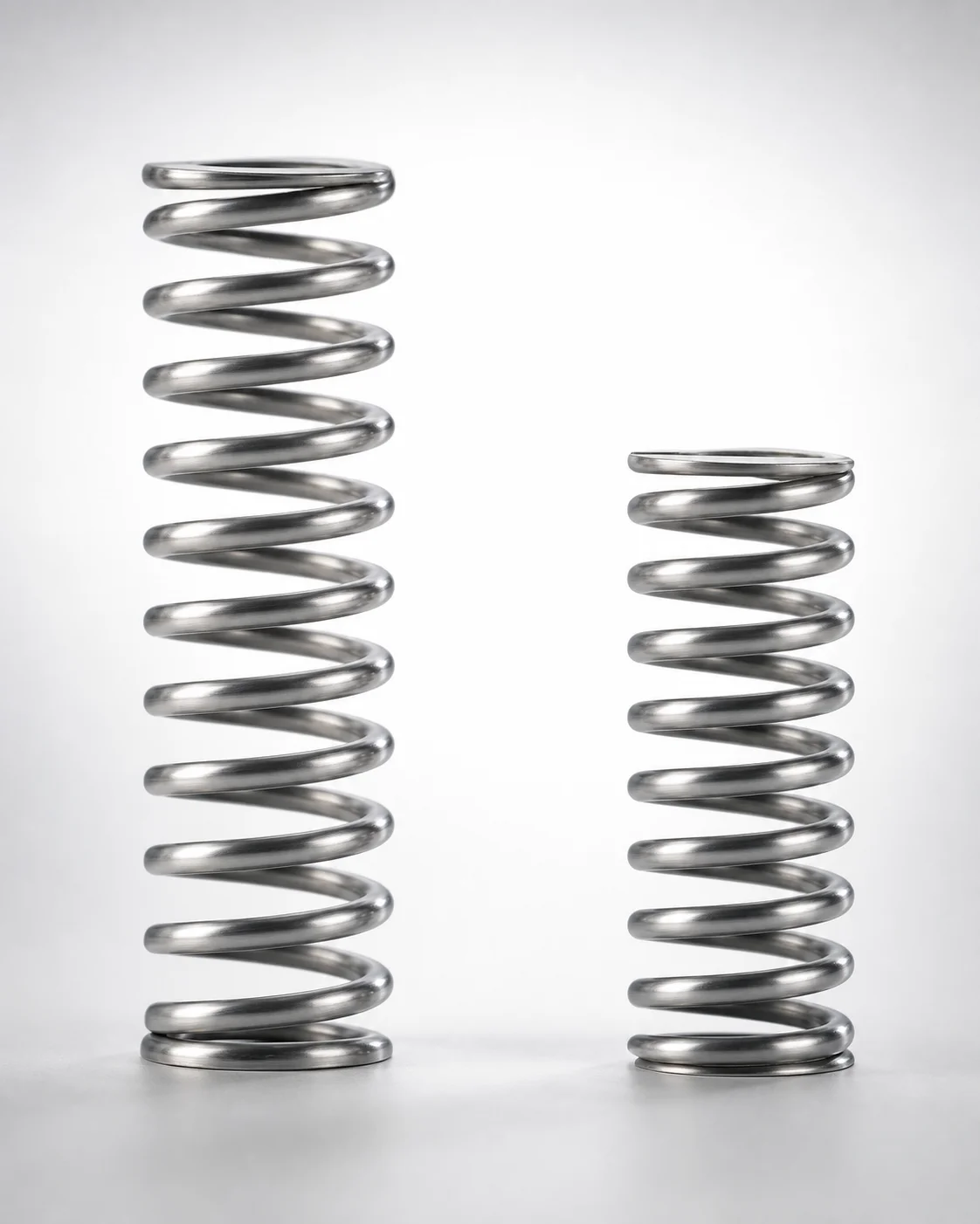
WHH Series 35% Deflection Heat Resistant Coil Spring
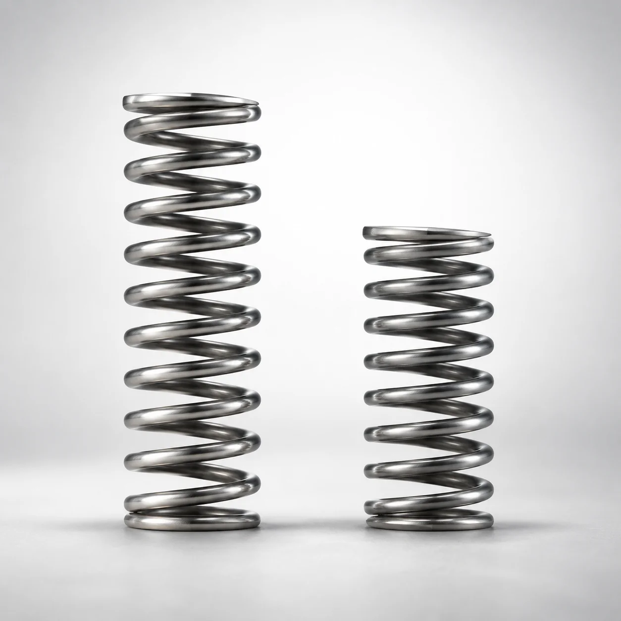
Heat Resistant Round Wire Spring 40% Deflection (WMH Series)
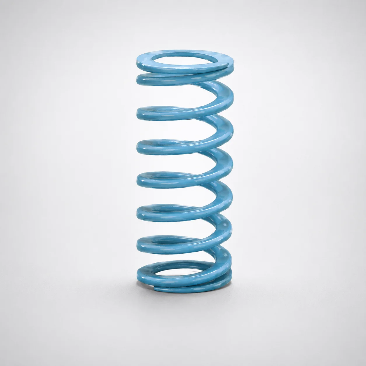
Super-High Deflection Coil Spring - 60% Deflection
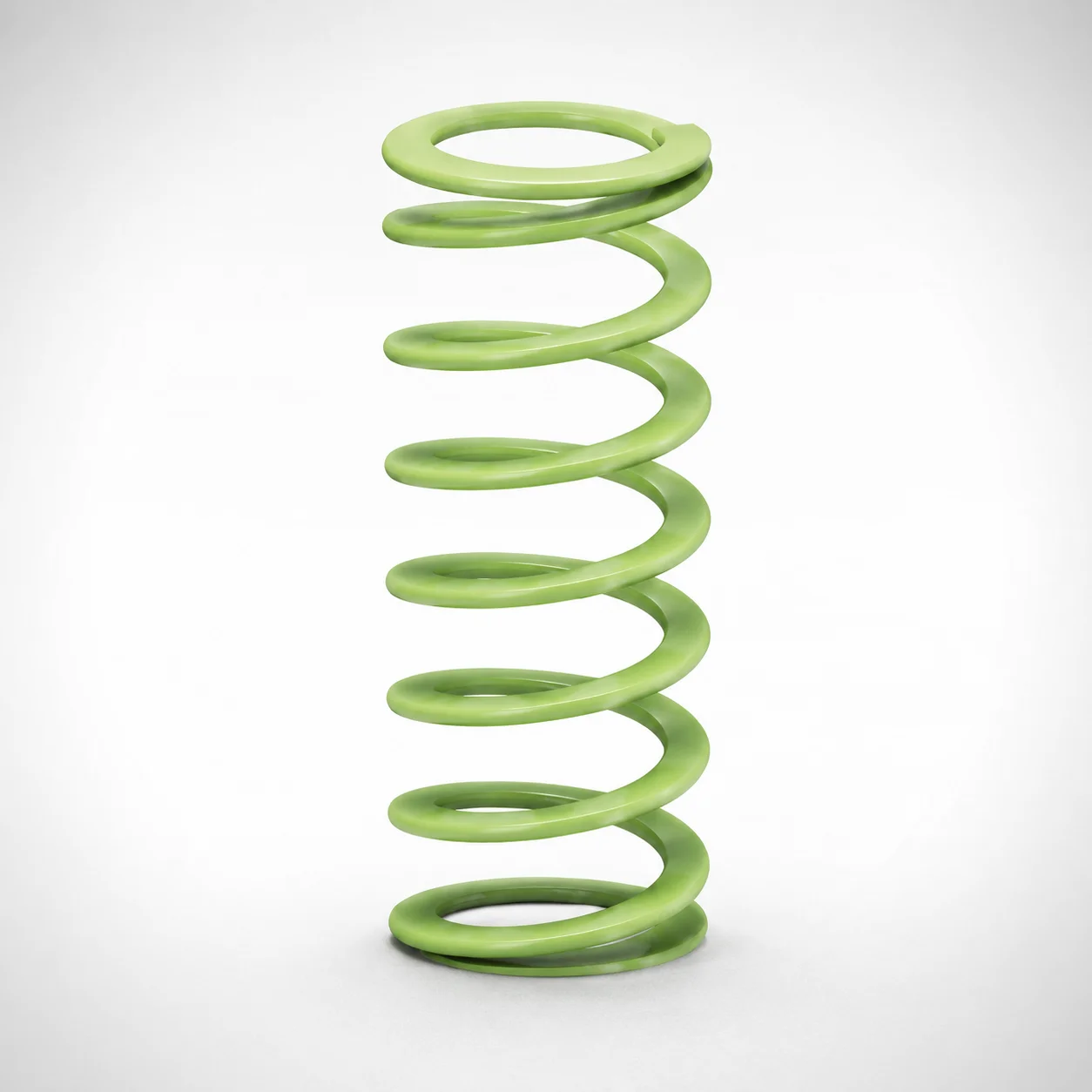
Ultra-High Deflection Coil Springs - 65% Deflection SWY Series
Need Custom Specifications?
Our engineering team can help with custom configurations, material selection, and volume pricing.