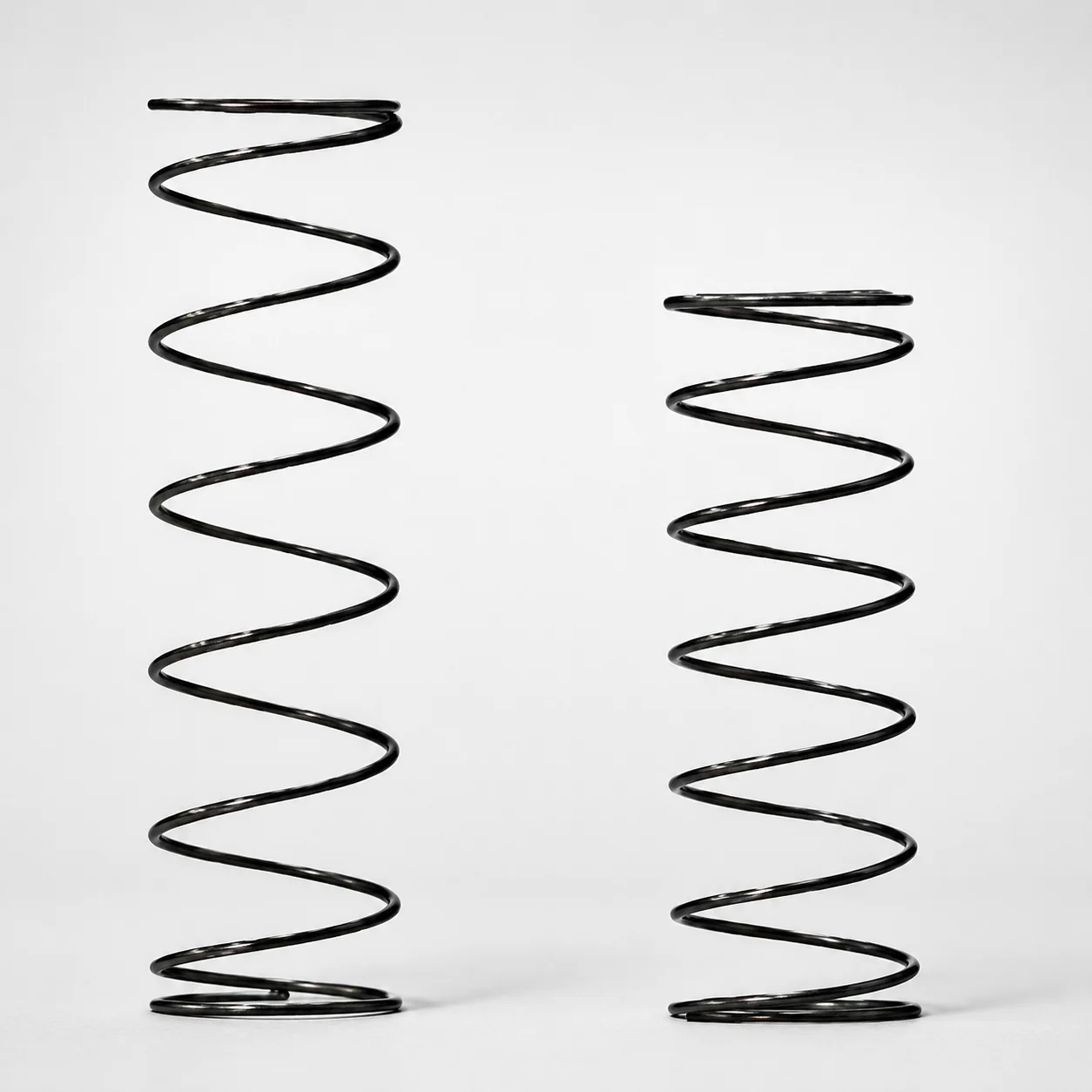
Heat Resistant Round Wire Spring - 60% Deflection (WFH Series)
Heat Resistant Round Wire Spring - 60% Deflection (WFH Series) is engineered to maintain consistent spring behavior in high-temperature environments up to 200°C. The WFH design targets dependable force response for precision compression applications.
- WFH spring type supports controlled 60% deflection for stable load characteristics
- Heat-resistant construction rated to 200°C helps prevent performance drift under heat
- Round wire coil geometry provides predictable compression behavior for assembly consistency
- Typical use in industrial mechanisms requiring temperature-tolerant spring force
Specifications
103 configurations available
| D (Diameter) (mm) | L (Length) (mm) | Spring Constant (N/mm) | Load (N) | Allowable Deflection (mm) | type |
|---|---|---|---|---|---|
| 4 | 5 | 0.5 | 1.5 | 3 | - |
| 4 | 10 | 0.5 | 2.9 | 6 | - |
| 4 | 15 | 0.5 | 4.4 | 9 | - |
| 4 | 20 | 0.5 | 5.9 | 12 | - |
| 4 | 25 | 0.5 | 7.4 | 15 | - |
| 4 | 30 | 0.5 | 8.8 | 18 | - |
| 4 | 35 | 0.5 | 10.3 | 21 | - |
| 4 | 40 | 0.5 | 11.8 | 24 | - |
| 5 | 5 | 0.5 | 1.5 | 3 | - |
| 5 | 10 | 0.5 | 2.9 | 6 | - |
| 5 | 15 | 0.5 | 4.4 | 9 | - |
| 5 | 20 | 0.5 | 5.9 | 12 | - |
| 5 | 25 | 0.5 | 7.4 | 15 | - |
| 5 | 30 | 0.5 | 8.8 | 18 | - |
| 5 | 35 | 0.5 | 10.3 | 21 | - |
| 5 | 40 | 0.5 | 11.8 | 24 | - |
| 5 | 45 | 0.5 | 13.2 | 27 | - |
| 5 | 50 | 0.5 | 14.7 | 30 | - |
| 6 | 5 | 0.5 | 1.5 | 3 | - |
| 6 | 10 | 0.5 | 2.9 | 6 | - |
| 6 | 15 | 0.5 | 4.4 | 9 | - |
| 6 | 20 | 0.5 | 5.9 | 12 | - |
| 6 | 25 | 0.5 | 7.4 | 15 | - |
| 6 | 30 | 0.5 | 8.8 | 18 | - |
| 6 | 35 | 0.5 | 10.3 | 21 | - |
| 6 | 40 | 0.5 | 11.8 | 24 | - |
| 6 | 45 | 0.5 | 13.2 | 27 | - |
| 6 | 50 | 0.5 | 14.7 | 30 | - |
| 6 | 55 | 0.5 | 16.2 | 33 | - |
| 6 | 60 | 0.5 | 17.7 | 36 | - |
| 6 | 65 | 0.5 | 19.1 | 39 | - |
| 6 | 70 | 0.5 | 20.6 | 42 | - |
| 6 | 80 | 0.5 | 23.5 | 48 | - |
| 8 | 10 | 0.5 | 2.9 | 6 | - |
| 8 | 15 | 0.5 | 4.4 | 9 | - |
| 8 | 20 | 0.5 | 5.9 | 12 | - |
| 8 | 25 | 0.5 | 7.4 | 15 | - |
| 8 | 30 | 0.5 | 8.8 | 18 | - |
| 8 | 35 | 0.5 | 10.3 | 21 | - |
| 8 | 40 | 0.5 | 11.8 | 24 | - |
| 8 | 45 | 0.5 | 13.2 | 27 | - |
| 8 | 50 | 0.5 | 14.7 | 30 | - |
| 8 | 55 | 0.5 | 16.2 | 33 | - |
| 8 | 60 | 0.5 | 17.7 | 36 | - |
| 8 | 65 | 0.5 | 19.1 | 39 | - |
| 8 | 70 | 0.5 | 20.6 | 42 | - |
| 8 | 80 | 0.5 | 23.5 | 48 | - |
| 10 | 10 | 0.5 | 2.9 | 6 | - |
| 10 | 15 | 0.5 | 4.4 | 9 | - |
| 10 | 20 | 0.5 | 5.9 | 12 | - |
Product Guide
Application Scenarios+
This high-temperature coil spring accessory is used inside injection mold assemblies wherever a repeatable compression force is required under elevated ambient conditions.
- Hot runner and heated manifold tooling: the WFH-style round wire geometry helps maintain stable spring response when nearby zones approach 200°C, supporting consistent return or contact force during cycling.
- Automotive connector or housing molds: springs are often used to support ejector-related motions or gate/locator mechanisms; the controlled 60% deflection target provides predictable load behavior for reliable actuation.
- Precision actuator fixtures and mold inserts: engineers can size the spring to match required compression travel; the specified allowable deflection range (see sizing guide) helps reduce force drift that can occur from thermal effects.
Because the variant is rated to 200°C and designed around controlled deflection, it is suited for tooling that prioritizes consistent force under heat rather than ultra-low deflection variability.
Material & Process Details+
The provided specifications confirm heat-resistant performance up to 200°C, but do not specify the exact steel grade, surface treatment, hardness level, or heat-treatment process for this WFH series.
Accordingly, the material section focuses on functional requirements relevant to mold spring selection: maintaining force stability during compression and preventing performance drift at temperature. In general, spring steels achieve the needed balance between wear resistance and toughness through appropriate quenching and tempering or nitriding, but those details are not listed for this SKU.
- Heat resistance: stable behavior targeted at 200°C.
- Performance trade-off: increased hardness typically improves resistance to permanent set, but can reduce toughness if over-tempered; verify with the manufacturer for the exact hardness/HRC for high-load cycles.
If you need hardness (HRC) or the specific grade (e.g., SKD61/H13 equivalent), share your drawing requirement and we can align the correct material specification.
Sizing & Selection Guide+
Select the spring by mapping required compression travel and force to the available D (diameter), L (length), and spring characteristics.
- Choose diameter (D): available 4 ~ 18 mm. Larger D generally supports higher loads for a given design, while also affecting packaging space in the mold.
- Choose free length (L): available 5 ~ 100 mm. Ensure the installed length in the cavity/core space allows the required deflection without coil bind.
- Verify allowable deflection: allowable deflection is 3 ~ 60 mm. Match your required stroke/travel so the working deflection stays inside this band.
- Match force requirements: load range is 1.5 ~ 58.8 N. Use the provided spring constant options (0.5 or 1.0 N/mm) and compute load = k × deflection to confirm the working point.
Deflection target for the series is 60% deflection; therefore, when you translate mold motion into spring compression, target the operating point around that fraction of the spring’s design capability. Tolerance/fit guidance is not provided in the input data—confirm fit clearances to prevent side loading in the spring seat.
Frequently Asked Questions
For the WFH series, what working deflection range should I design around to stay within allowable limits?+
How do I calculate the expected spring load for this spring when sizing an ejector or contact mechanism?+
What spring dimensions are available for this series, and how do I pick between D and L?+
Is this spring suitable for mold areas exposed to around 200°C, and what does “heat resistant” imply for force stability?+
What material grade and hardness (HRC) are used, and are there surface treatments like nitriding?+
Related Products
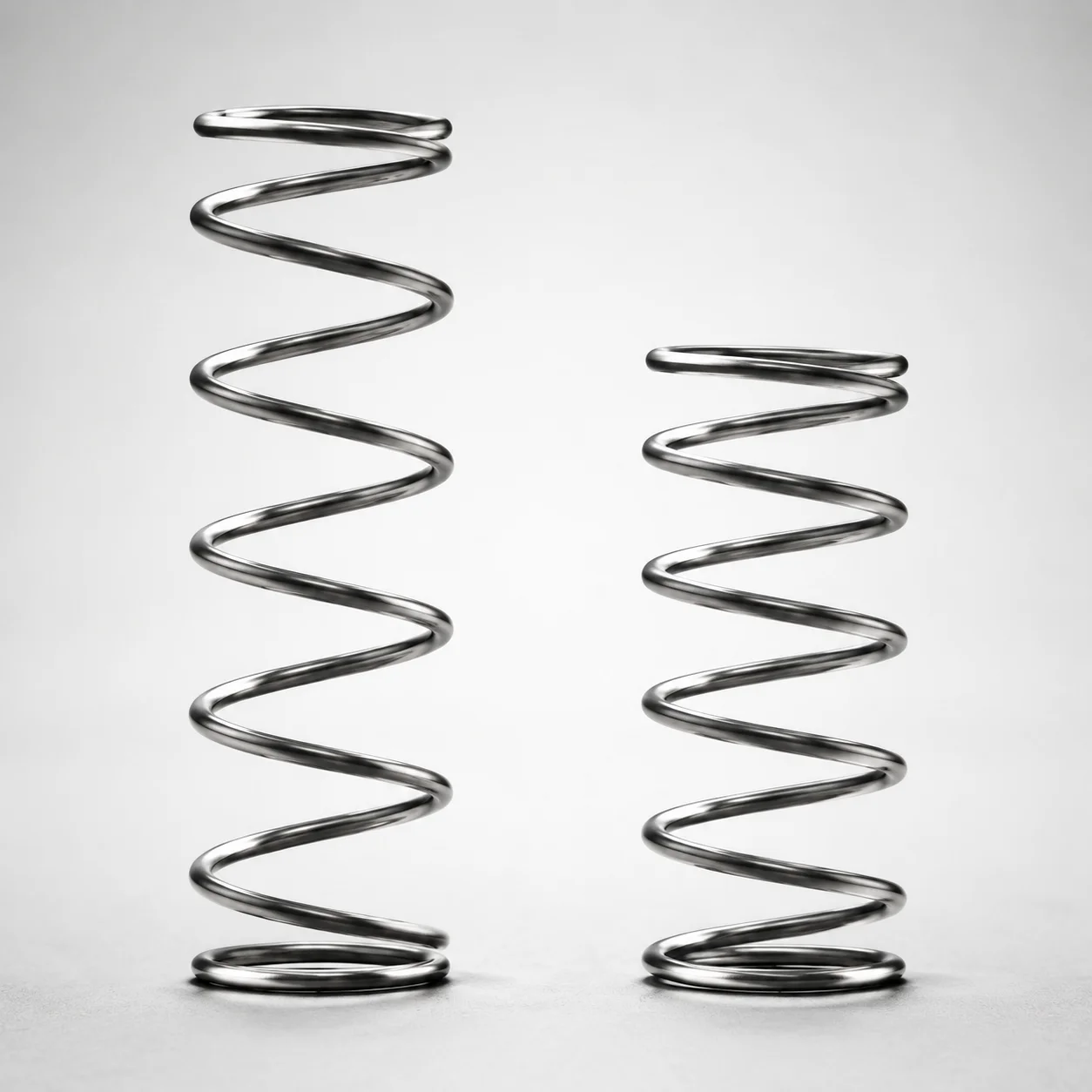
WLH Series Heat Resistant Round Wire Spring - 50% Deflection
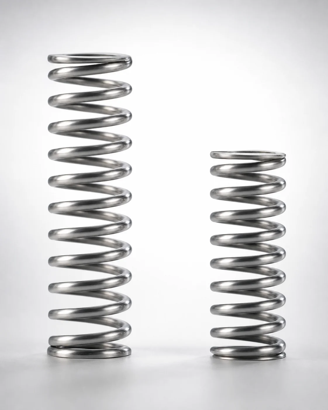
WHH Series 35% Deflection Heat Resistant Coil Spring
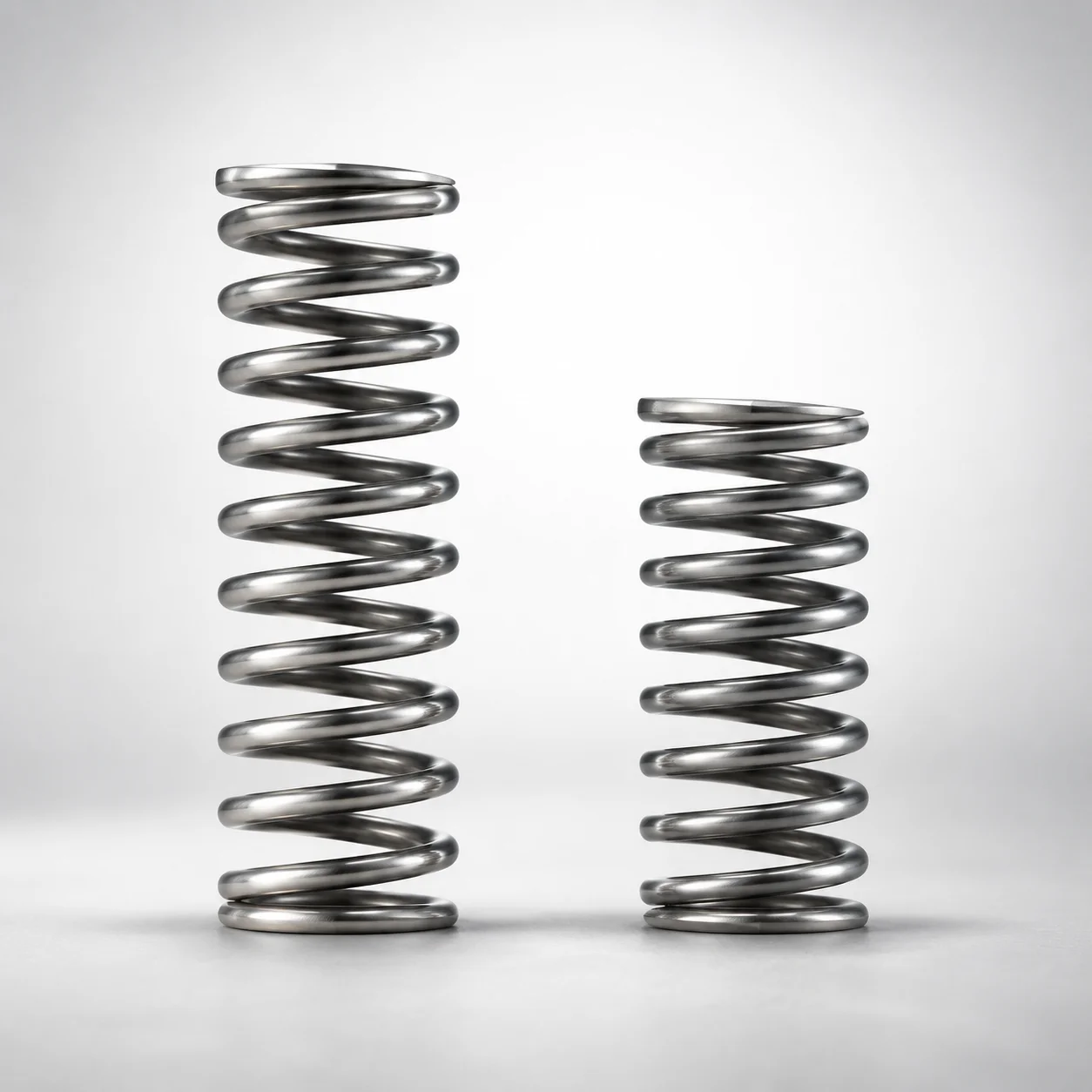
Heat Resistant Round Wire Spring 40% Deflection (WMH Series)
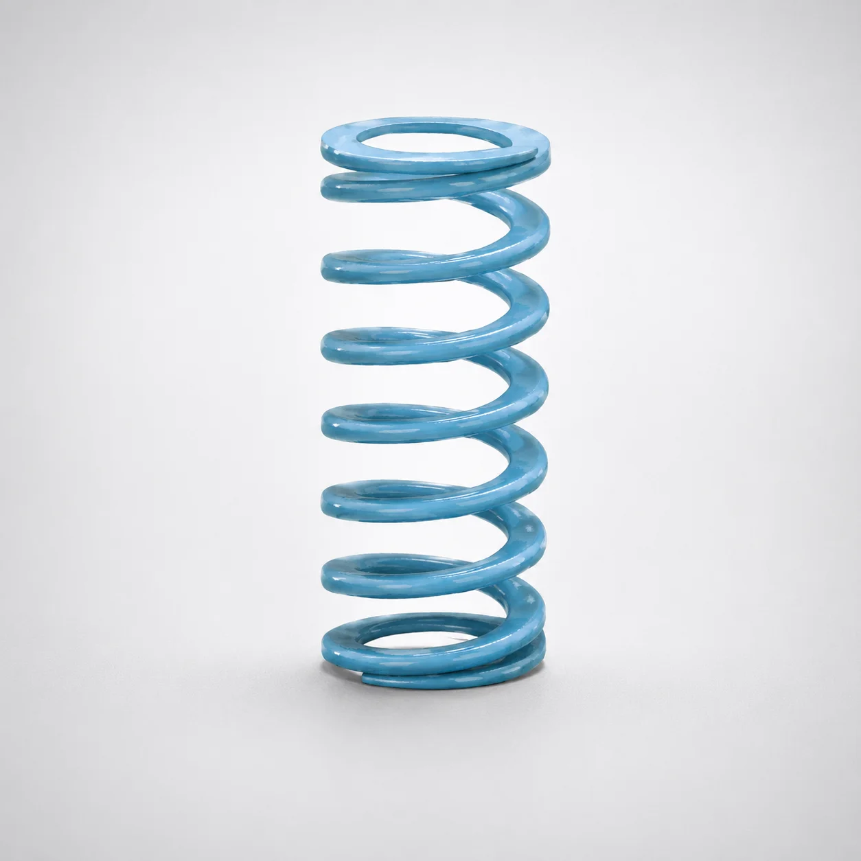
Super-High Deflection Coil Spring - 60% Deflection
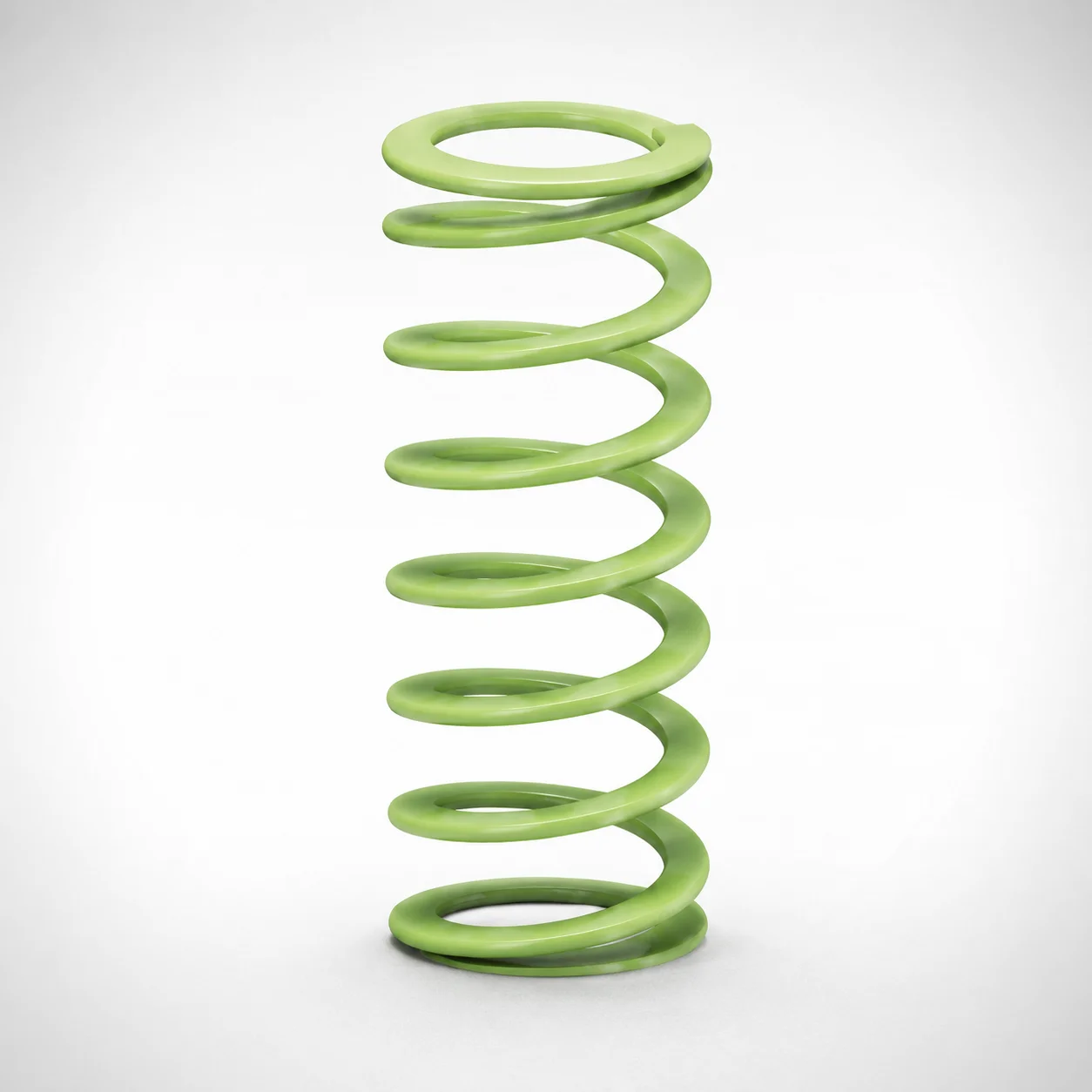
Ultra-High Deflection Coil Springs - 65% Deflection SWY Series
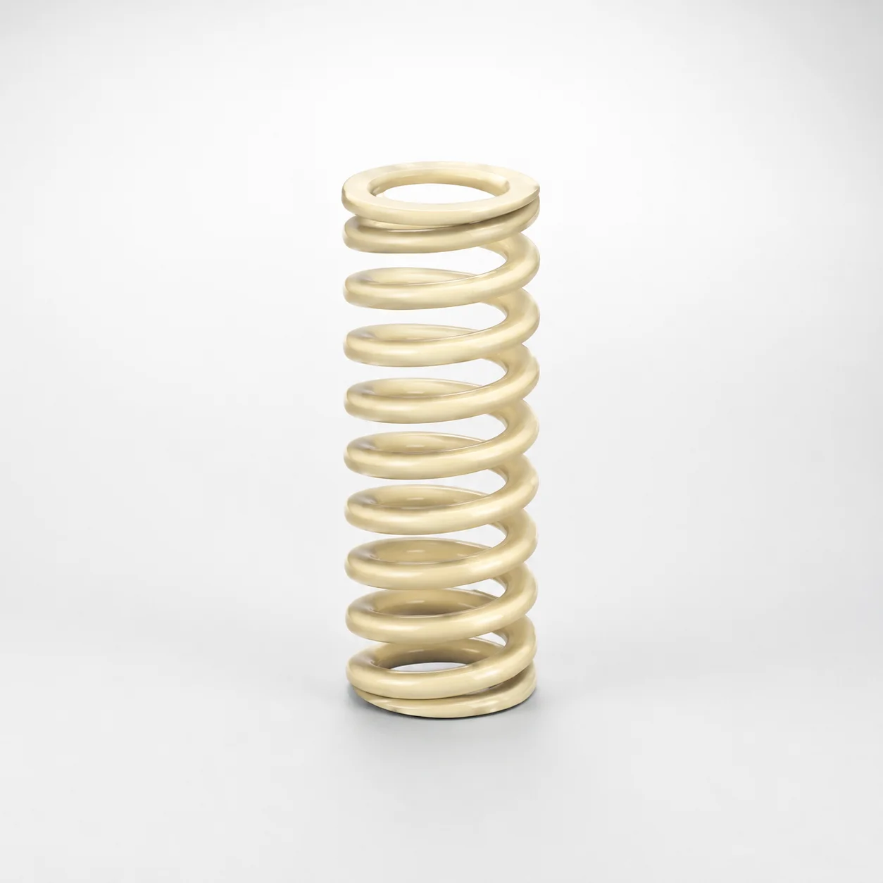
High Deflection Coil Springs (50% Deflection) SWR Series
Need Custom Specifications?
Our engineering team can help with custom configurations, material selection, and volume pricing.