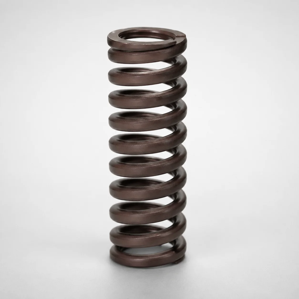
Low Deflection Coil Spring - 30% Deflection, SWN Series
Low Deflection Coil Spring - 30% Deflection, SWN Series (flat wire type) is designed to maintain stable spring characteristics under controlled deflection for precision machinery. With heat resistance up to 200°C, it helps reduce performance drift in demanding operating conditions.
- 30% deflection design supports low deflection force stability
- Flat wire construction improves spring behavior for compact assemblies
- Heat resistant to 200°C for reliable operation in warm environments
- Use in industrial mechanisms requiring consistent load and controlled movement
Specifications
254 configurations available
| D (Diameter) (mm) | L (Length) (mm) | d (Inner Diameter - Flat Type Only) | Spring Constant (N/mm) | Load (N) | Allowable Deflection (mm) | With/without paint peeling | type |
|---|---|---|---|---|---|---|---|
| 14.5 | 20 | 8.5 | 45.76 | 274.6 | 6 | Yes | - |
| 14.5 | 25 | 8.5 | 36.61 | 274.6 | 7.5 | Yes | - |
| 14.5 | 30 | 8.5 | 30.51 | 274.6 | 9 | Yes | - |
| 14.5 | 35 | 8.5 | 26.15 | 274.6 | 10.5 | Yes | - |
| 14.5 | 40 | 8.5 | 22.88 | 274.6 | 12 | Yes | - |
| 14.5 | 45 | 8.5 | 20.34 | 274.6 | 13.5 | Yes | - |
| 14.5 | 50 | 8.5 | 18.31 | 274.6 | 15 | Yes | - |
| 14.5 | 55 | 8.5 | 16.64 | 274.6 | 16.5 | Yes | - |
| 14.5 | 60 | 8.5 | 15.25 | 274.6 | 18 | Yes | - |
| 14.5 | 65 | 8.5 | 14.08 | 274.6 | 19.5 | Yes | - |
| 14.5 | 70 | 8.5 | 13.08 | 274.6 | 21 | Yes | - |
| 14.5 | 75 | 8.5 | 12.20 | 274.6 | 22.5 | Yes | - |
| 14.5 | 80 | 8.5 | 11.44 | 274.6 | 24 | Yes | - |
| 14.5 | 90 | 8.5 | 10.17 | 274.6 | 27 | Yes | - |
| 14.5 | 100 | 8.5 | 9.15 | 274.6 | 30 | Yes | - |
| 14.5 | 125 | 8.5 | 7.32 | 274.6 | 37.5 | Yes | - |
| 14.5 | 150 | 8.5 | 6.10 | 274.6 | 45 | Yes | - |
| 17 | 25 | 10.5 | 49.69 | 372.7 | 7.5 | Yes | - |
| 17 | 30 | 10.5 | 41.41 | 372.7 | 9 | Yes | - |
| 17 | 35 | 10.5 | 35.49 | 372.7 | 10.5 | Yes | - |
| 17 | 40 | 10.5 | 31.05 | 372.7 | 12 | Yes | - |
| 17 | 45 | 10.5 | 27.60 | 372.7 | 13.5 | Yes | - |
| 17 | 50 | 10.5 | 24.84 | 372.7 | 15 | Yes | - |
| 17 | 55 | 10.5 | 22.59 | 372.7 | 16.5 | Yes | - |
| 17 | 60 | 10.5 | 20.70 | 372.7 | 18 | Yes | - |
| 17 | 65 | 10.5 | 19.11 | 372.7 | 19.5 | Yes | - |
| 17 | 70 | 10.5 | 17.75 | 372.7 | 21 | Yes | - |
| 17 | 75 | 10.5 | 16.56 | 372.7 | 22.5 | Yes | - |
| 17 | 80 | 10.5 | 15.53 | 372.7 | 24 | Yes | - |
| 17 | 90 | 10.5 | 13.80 | 372.7 | 27 | Yes | - |
| 17 | 100 | 10.5 | 12.42 | 372.7 | 30 | Yes | - |
| 17 | 125 | 10.5 | 9.94 | 372.7 | 37.5 | Yes | - |
| 17 | 150 | 10.5 | 8.28 | 372.7 | 45 | Yes | - |
| 21 | 30 | 13.5 | 54.48 | 490.3 | 9 | Yes | - |
| 21 | 35 | 13.5 | 46.70 | 490.3 | 10.5 | Yes | - |
| 21 | 40 | 13.5 | 40.86 | 490.3 | 12 | Yes | - |
| 21 | 45 | 13.5 | 36.32 | 490.3 | 13.5 | Yes | - |
| 21 | 50 | 13.5 | 32.69 | 490.3 | 15 | Yes | - |
| 21 | 55 | 13.5 | 29.72 | 490.3 | 16.5 | Yes | - |
| 21 | 60 | 13.5 | 27.24 | 490.3 | 18 | Yes | - |
| 21 | 65 | 13.5 | 25.15 | 490.3 | 19.5 | Yes | - |
| 21 | 70 | 13.5 | 23.35 | 490.3 | 21 | Yes | - |
| 21 | 75 | 13.5 | 21.79 | 490.3 | 22.5 | Yes | - |
| 21 | 80 | 13.5 | 20.43 | 490.3 | 24 | Yes | - |
| 21 | 90 | 13.5 | 18.16 | 490.3 | 27 | Yes | - |
| 21 | 100 | 13.5 | 16.34 | 490.3 | 30 | Yes | - |
| 21 | 110 | 13.5 | 14.86 | 490.3 | 33 | Yes | - |
| 21 | 120 | 13.5 | 13.62 | 490.3 | 36 | Yes | - |
| 21 | 125 | 13.5 | 13.08 | 490.3 | 37.5 | Yes | - |
| 21 | 130 | 13.5 | 12.57 | 490.3 | 39 | Yes | - |
Product Guide
Application Scenarios+
This low-deflection coil spring variant is used inside plastic injection mold auxiliary mechanisms where repeatable force under stroke is critical. A common scenario is in precision actuator assemblies for connector and latch tooling, where stable return force helps maintain consistent pin, slide, or lifter timing across cycles.
Another practical application is wear-tolerant control systems in hot or warm production cells. With heat resistance up to 200°C and a design focused on controlled deflection (30% deflection basis), it helps limit performance drift when tooling temperature rises.
- Flat wire option supports compact packaging and controlled spring behavior in limited envelope spaces.
- Industrial mechanisms benefit from the stable spring characteristics produced by the low-deflection design and predictable load/deflection profile.
- With/without paint peeling availability supports compatibility with different finishing and cleanliness requirements.
Material & Process Details+
The provided metadata does not specify a steel grade, heat-treatment route (e.g., quenched & tempered, nitrided), or exact hardness (HRC) for this SWN low-deflection coil spring. Therefore, those parameters cannot be stated reliably from the current dataset.
What can be supported is the performance target: low deflection with stable force and heat resistance up to 200°C. In spring engineering terms, achieving this stability typically involves selecting an appropriate spring steel and applying heat treatment to balance wear resistance (surface durability) and toughness (resistance to cracking under cyclic loading).
- Flat wire construction is intended to improve spring behavior in compact assemblies by promoting more predictable deflection response.
- If your application requires specific hardness/HRC or surface treatment, confirm the steel/heat-treatment specification from the supplier’s technical sheet.
- Paint-peeling options (Yes/No) indicate different surface/finish conditions that may affect corrosion resistance and appearance in sensitive mechanisms.
Sizing & Selection Guide+
Select the spring by matching its outer diameter D, length L, and required deflection capacity to the molded mechanism stroke and packaging constraints. Available D values are 14.5, 17, 21, 26, 31, 37 mm, and L is 20 to 300 mm.
If using the flat wire type, also confirm the inner diameter d (flat type only): 8.5, 10.5, 13.5, 16.5, 21, 26 mm. This ensures proper alignment around shafts, guide rods, or core/cavity-related hardware.
- Verify that the required working stroke stays within the allowable deflection range of 6 to 90 mm.
- Use the stated spring constant (6.1 to 76.27 N/mm) to estimate load at your target deflection; published load values (e.g., 274.6, 372.7, 490.3, 686.5, 833.6, 882.6 N) can be used directly for quick selection.
- Tight-fit requirements should consider that selection is by nominal dimensions; for critical fits, validate assembly clearances with your specific guide/retainer geometry.
- Choose with/without paint peeling to match your surface-condition requirements for the mold system.
Frequently Asked Questions
How do I confirm the spring will remain within allowable stroke for a mold actuator mechanism?+
For the flat wire version, which inner diameter d values are available and how do they affect installation on guides?+
What load should I expect at a given deflection when designing a return force for tooling?+
Is this spring suitable for warm production environments, and what thermal limit is specified?+
Does the finish condition (paint peeling) change how I should specify or handle the spring in a mold build?+
Related Products
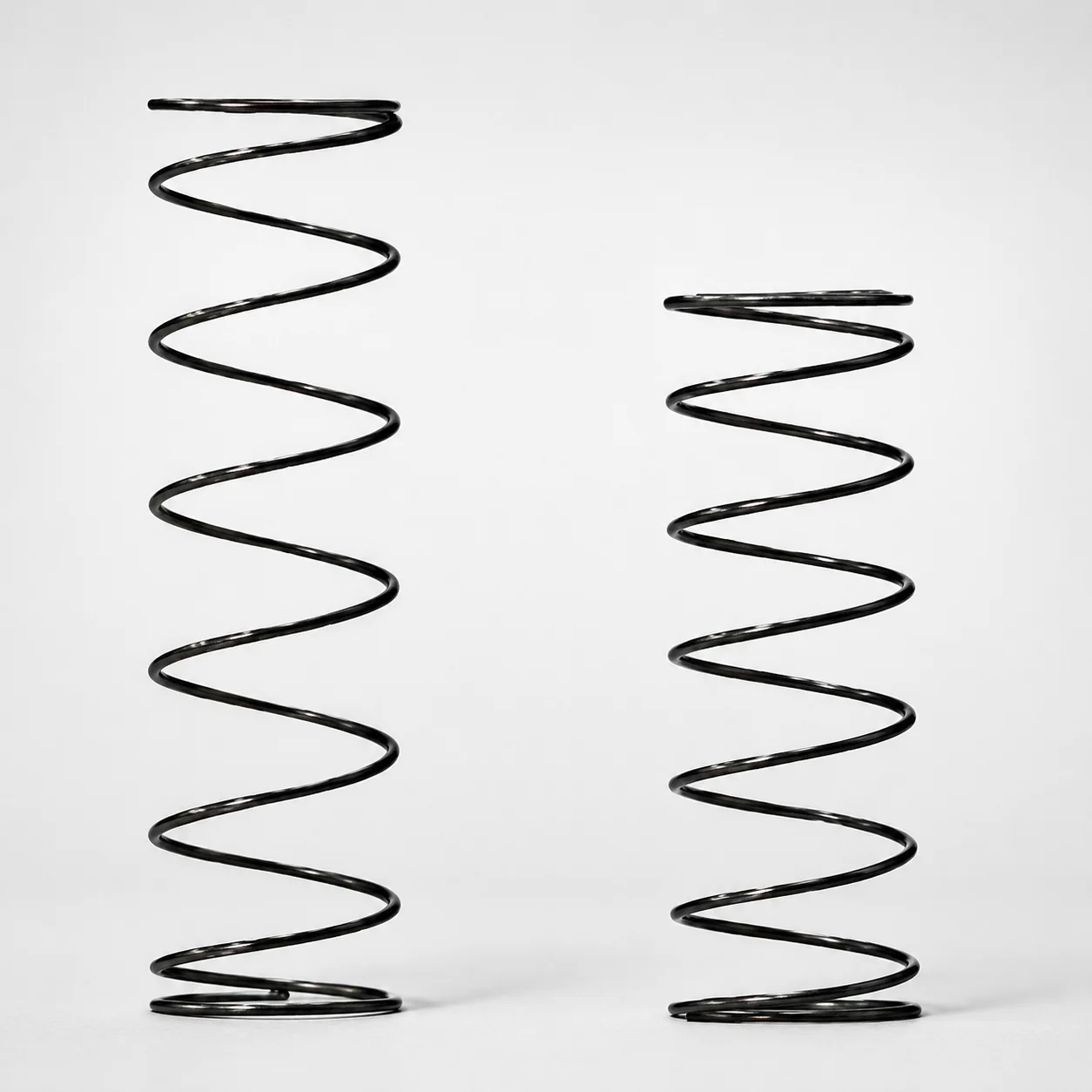
Heat Resistant Round Wire Spring - 60% Deflection (WFH Series)
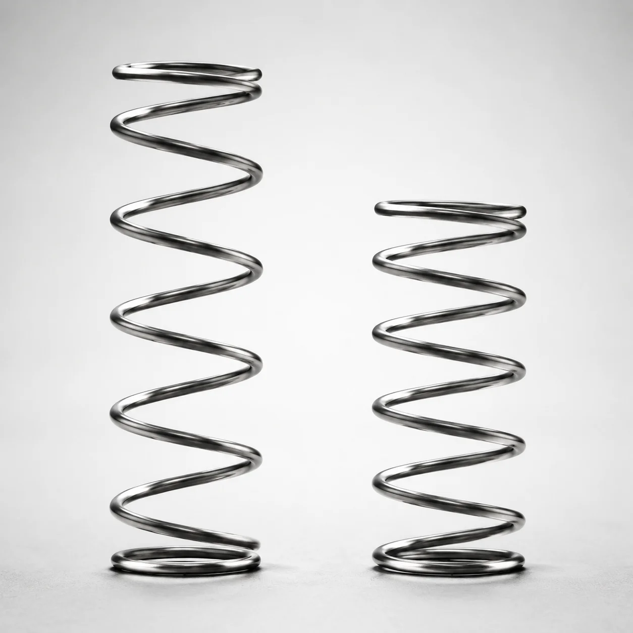
WLH Series Heat Resistant Round Wire Spring - 50% Deflection
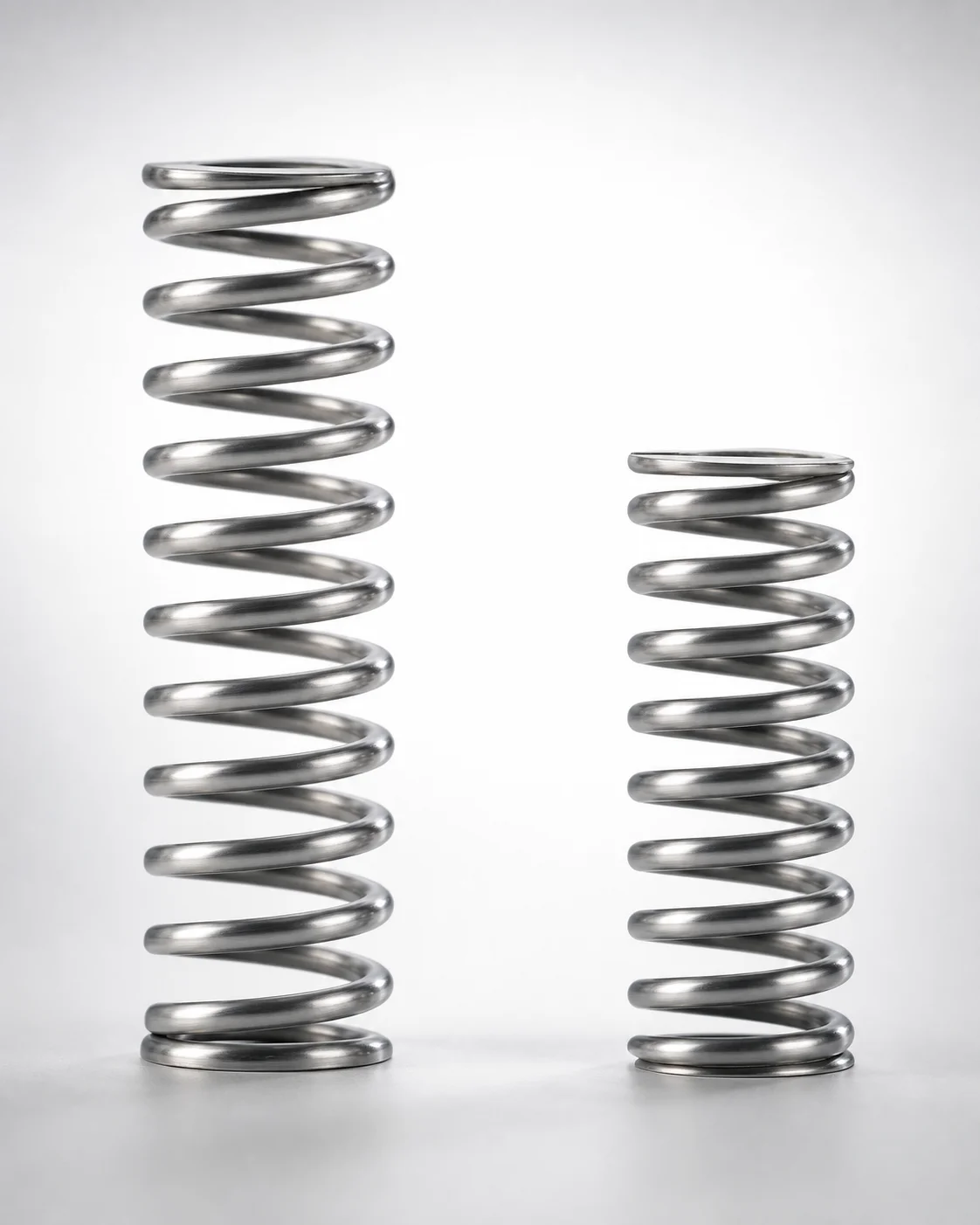
WHH Series 35% Deflection Heat Resistant Coil Spring
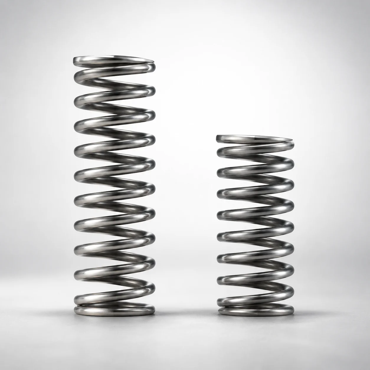
Heat Resistant Round Wire Spring 40% Deflection (WMH Series)
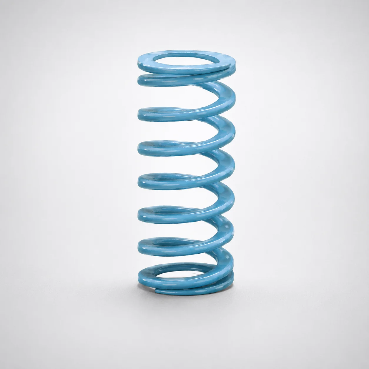
Super-High Deflection Coil Spring - 60% Deflection
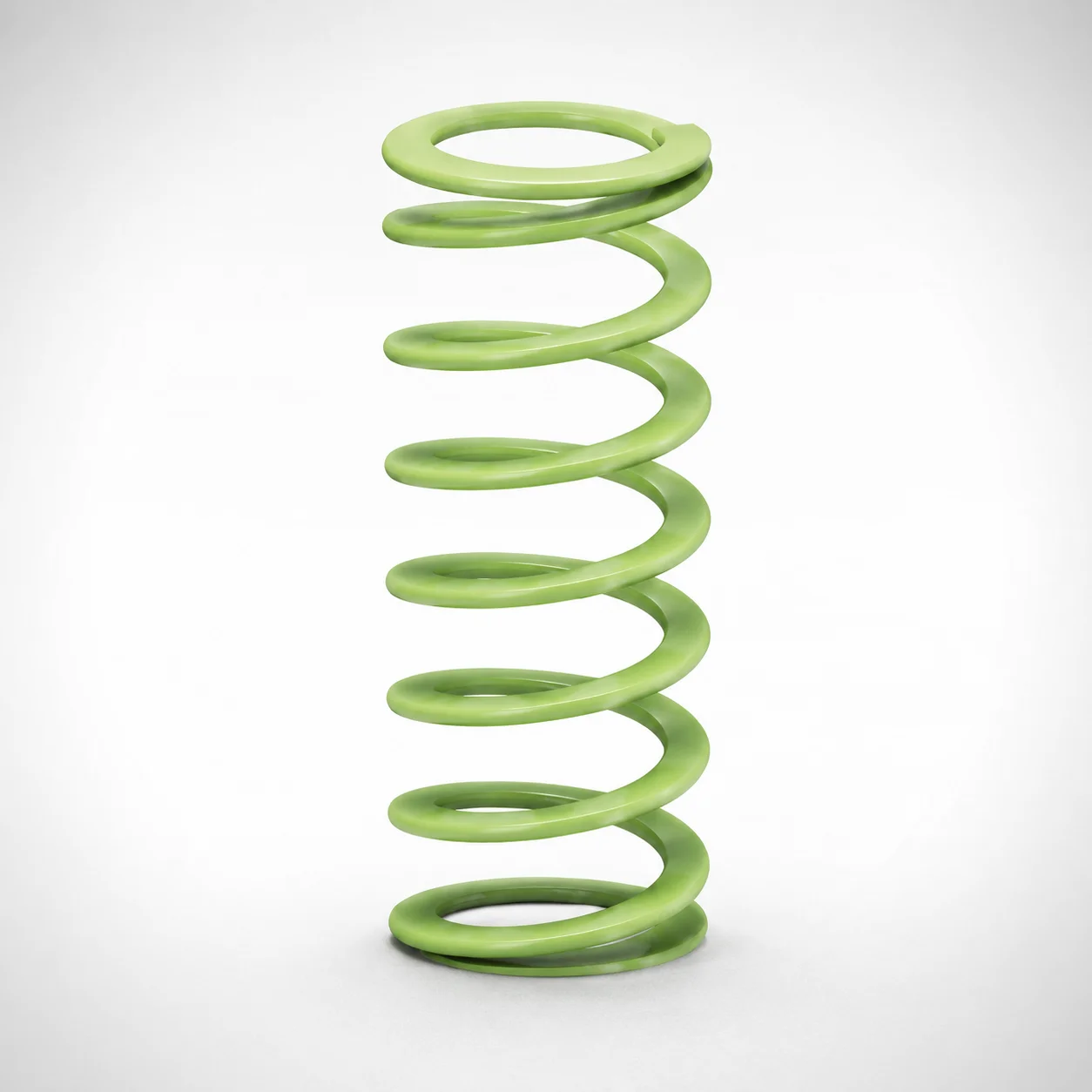
Ultra-High Deflection Coil Springs - 65% Deflection SWY Series
Need Custom Specifications?
Our engineering team can help with custom configurations, material selection, and volume pricing.