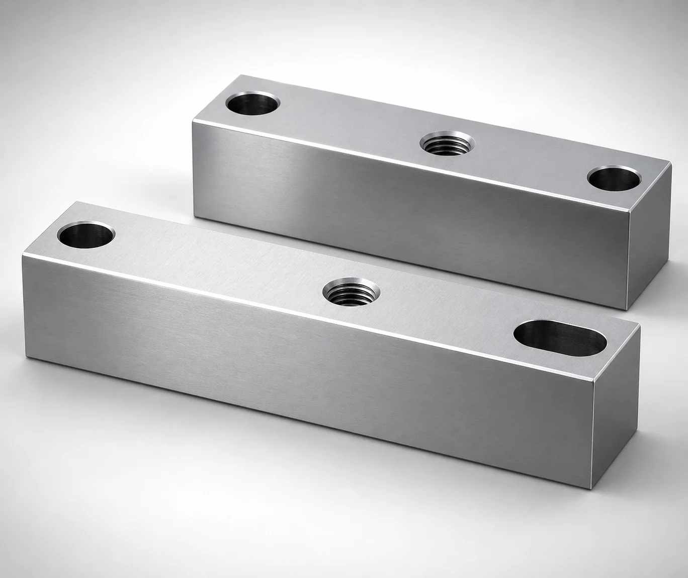
Lifting Bars for Mold Two-Plate or Three-Plate
Lifting Bars for Mold Two-Plate or Three-Plate are designed to support safe, stable mold handling during installation and maintenance. They help streamline crane operations while reducing wear on critical mold components.
- Compatible for both two-plate and three-plate mold structures
- Threaded tap interface supports reliable lifting attachment
- Precision hole geometry helps maintain correct positioning and alignment
- Durable construction for frequent use in production environments
Specifications
6 configurations available
| Applications | M (Tap diameter) (mm) | C (Hole position) (mm) | E (Tap hole position) (mm) | H (Inter-hole pitch) (mm) | L (L dimension) (mm) | S (Slotted hole pitch) (mm) | type |
|---|---|---|---|---|---|---|---|
| For two-plate mold | 12 | 9 ~ 20 | 49 ~ 175 | 9 ~ 332 | 100 ~ 350 | - | - |
| For two-plate mold | 16 | 12 ~ 25 | 62 ~ 230 | 70 ~ 436 | 124 ~ 460 | - | - |
| For two-plate mold | 20 | 15 ~ 25 | 75 ~ 235 | 100 ~ 440 | 150 ~ 470 | - | - |
| For three-plate mold | 12 | 9 ~ 20 | 49 ~ 175 | 60 ~ 332 | 100 ~ 350 | 1 ~ 15 | - |
| For three-plate mold | 16 | 12 ~ 25 | 62 ~ 230 | 70 ~ 436 | 125 ~ 460 | 1 ~ 15 | - |
| For three-plate mold | 20 | 15 ~ 25 | 75 ~ 235 | 100 ~ 440 | 150 ~ 470 | 1 ~ 15 | - |
Product Guide
Application Scenarios+
These lifting bars are used in industrial injection mold tooling to support safe transport, installation, and maintenance of two-plate or three-plate molds. During crane handling, the threaded tap interface provides a repeatable attachment point so the sling/eye connection can be positioned consistently, helping maintain alignment as the mold is brought into the press.
- Two-plate mold handling: Select the variant with the tap diameter (M) and hole offsets (C, E) matched to your mold lifting bosses to ensure the bars land correctly and avoid side-loading.
- Three-plate mold positioning: Use the specified inter-hole pitch (H) and slotted hole pitch (S) range to accommodate thicker structures while keeping the lifting attachment geometry stable during maintenance.
- Production environment servicing: The durable, precision hole geometry supports frequent use where consistent positioning reduces downtime caused by rework and realignment.
Material & Process Details+
The provided metadata does not specify a steel grade, hardness (HRC), heat treatment state, or surface treatments for this lifting bar series. Because these parameters are not listed, Axiom Molds only recommends selecting the correct dimensional variant based on tap diameter and hole geometry.
- Material selection: If you have a preferred alloy (e.g., through-hardened or nitrided options) for your workshop standards, confirm compatibility with your lifting hardware and load case.
- Heat treatment: No pre-hardened, quenched-and-tempered, or nitrided conditions are specified in the input data, so treat heat-treatment characteristics as unspecified for this SKU.
- Wear/toughness trade-offs: Lifting bars experience repeated handling loads; however, wear resistance and toughness trade-offs cannot be stated without the specified steel and hardness.
For exact metallurgical properties (grade, HRC, and treatment), please request the material data sheet for series code 110200137220.
Sizing & Selection Guide+
Correct sizing is driven by matching the lifting bar geometry to the mold’s tap and lifting-boss hole layout. Use the tap diameter (M) first: available sizes are M = 12, 16, or 20 mm.
- Hole position matching: Confirm the C (hole position) range for your mold, depending on your chosen variant: 9–20, 12–25, or 15–25 mm. Then verify the E (tap hole position) against 49–175, 62–230, or 75–235 mm.
- Pitch and length constraints: Ensure the inter-hole pitch (H) matches your lifting-boss spacing (examples include 9–332 and up to 100–440 mm, depending on variant). Match the L (L dimension) to your available envelope: 100–350, 124–460, 150–470, or 125–460 mm.
- Slotted hole pitch: the fixed S = 1–15 mm should align with your hardware adjustment approach.
Because the dataset lists dimension ranges rather than single values, lock the final bar configuration to the exact mold drawings. Tolerance/fit details are not provided, so validate fit during trial assembly and confirm thread compatibility with your specified tap hardware.
Frequently Asked Questions
Which tap diameter (M) should I select for lifting a two-plate mold with this series?+
How do I verify compatibility between the lifting bar and a three-plate mold regarding hole spacing?+
What should I match first: C, E, or L, when selecting the correct lifting bar geometry?+
Is the slotted hole pitch (S) adjustable, and what range should I expect?+
Do you provide a single fixed dimension set, or do these bars come in multiple dimension ranges?+
Related Products
Need Custom Specifications?
Our engineering team can help with custom configurations, material selection, and volume pricing.