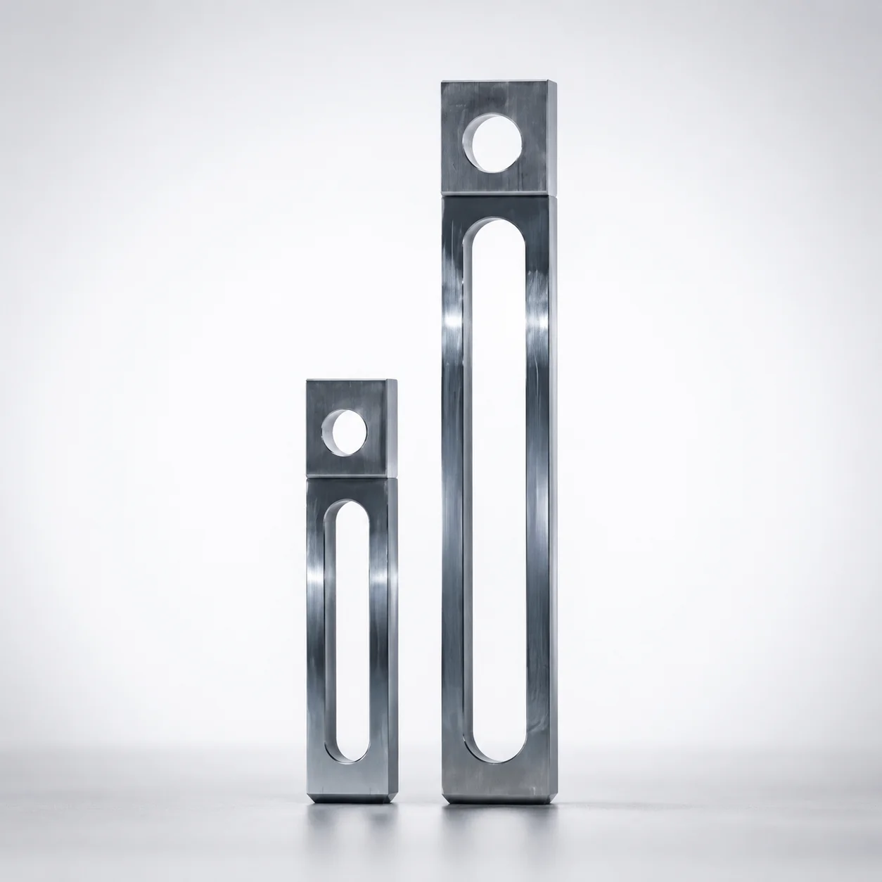
Stepped Tension Links Oval Hole Length (CB)
Stepped tension links for fixed-side CB socket head cap screws provide a rigid stepped structure with adjustable oval hole length, enabling controlled deflection in load transfer applications.
- Stepped design for predictable stiffness and stable tension link behavior under load
- Fixed-side mounting for socket head cap screw (CB) alignment and repeatable installation
- Configurable oval hole length to match stroke requirements in 5 mm increments
- Built for engineering loads with an allowable deflection ratio of 32%
Specifications
12 configurations available
| Mounting Method | Thickness (mm) | A (Tension Link Width) (mm) | S (Slotted hole pitch) (mm) | SC (S dimension alteration) (mm) | type |
|---|---|---|---|---|---|
| Fixed side: for socket head cap screw (CB) | 9 | 19 | 50 ~ 170 | - | - |
| Fixed side: for socket head cap screw (CB) | 9 | 25 | 50 ~ 200 | - | - |
| Fixed side: for socket head cap screw (CB) | 9 | 32 | 80 ~ 200 | - | - |
| Fixed side: for socket head cap screw (CB) | 9 | 38 | 100 ~ 200 | - | - |
| - | 16 | 19 | 50 ~ 270 | - | - |
| - | 16 | 19 | - | 51 ~ 269 | - |
| - | 16 | 25 | 50 ~ 270 | - | - |
| - | 16 | 25 | - | 51 ~ 269 | - |
| - | 16 | 32 | 80 ~ 300 | - | - |
| - | 16 | 32 | - | 81 ~ 299 | - |
| - | 16 | 38 | 100 ~ 350 | - | - |
| - | 16 | 38 | - | 101 ~ 349 | - |
Product Guide
Application Scenarios+
These stepped tension links are used in injection mold opening and load-transfer tooling where repeatable stiffness and controlled compliance are required. The fixed-side CB mounting aligns with fixed-side socket head cap screws, helping maintain consistent installation and predictable behavior cycle after cycle.
Automotive connector and housing molds often require stable gate/runner-related movement under varying clamp-cycle loads. The adjustable oval hole length (in 5 mm increments) lets designers tune the effective link compliance to manage misalignment tolerance and optimize opening timing.
Large-part medical device housings benefit when load must be transferred smoothly without excessive deflection that could affect sealing or surface finish. This variant supports controlled deflection up to 32%, making it suitable for managing engineering loads where a balance between compliance and stiffness is critical.
- Use fixed-side CB mounting to ensure alignment with socket head cap screws.
- Select oval hole length to match required stroke/control range.
- Apply where controlled compliance (up to 32%) improves stability under load.
Material & Process Details+
The provided product data does not specify a steel grade or heat treatment state (e.g., quenched & tempered, nitriding). As a result, the exact hardness in HRC, wear resistance rating, and toughness trade-offs cannot be stated from the available specifications.
For engineering selection, treat this as a geometry- and mounting-defined tension link component: the stepped form and oval hole-length adjustability govern stiffness and deflection response (allowable controlled deflection up to 32%).
- When integrating into a mold, confirm the supplier’s actual steel grade and heat treatment before finalizing load calculations.
- If multiple material options exist in your configuration, compare hardness for wear-critical duty and toughness for impact/shock loads.
- Validate that the chosen material meets your expected cycle life and any corrosion requirements in the molding environment.
Sizing & Selection Guide+
Select the tension link dimensions by matching the mechanical interface and the required stroke/control range in the mold opening controller assembly. Start with the fixed mounting method: this component is specified for the fixed side for socket head cap screw (CB), so it must pair with the corresponding screw interface on the fixed plate.
Next, choose the thickness and planform geometry to meet stiffness needs: Thickness is available as 9 mm or 16 mm, and width A is available as 19, 25, 32, or 38 mm.
Then set the motion/tuning parameters. The oval hole length is described as adjustable in 5 mm increments; use the required effective stroke or compliance target to determine the oval hole length. Select the slotted hole pitch S = 50 ~ 100 mm and the dimension alteration range SC from the provided options: 51–269 (with one configuration), 81–299, or 101–349.
- Confirm that the selected geometry keeps deflection within the specified 32% limit under maximum load.
- Verify fit with the CB socket head cap screw and the installed guide pitch; tolerance values are not provided, so use your drawing standards during design.
Frequently Asked Questions
How does the adjustable oval hole length influence deflection limits in tension link systems?+
This stepped tension link is designed with an adjustable oval hole length (set in 5 mm increments) so designers can tune the effective compliance of the load-transfer path. The product supports controlled deflection up to 32%, which should be checked against your maximum expected engineering load in the mold opening controller.
Which thickness and width options are available, and how do they affect stiffness selection?+
Thickness is specified as 9 mm or 16 mm. The tension link width A is available as 19, 25, 32, or 38 mm. In practice, larger thickness/width combinations typically increase stiffness, but the final selection should be verified with your deflection and alignment requirements.
What are the allowable ranges for slotted hole pitch (S) and SC dimension alteration?+
The slotted hole pitch is specified as S = 50 ~ 100 mm. For dimension alteration, the product lists multiple SC ranges: 51–269, 81–299, and 101–349. Choose the range that matches the controller linkage geometry and the required adjustment travel in your mold assembly.
Is this tension link intended for fixed-side installation only, and what screw interface does it use?+
Yes. The mounting method is specified as fixed side: for socket head cap screw (CB). This means it is intended to be installed on the fixed plate side with the CB socket head cap screw interface for repeatable alignment.
What material grade, hardness, and heat treatment should be assumed for this component?+
The provided specification data does not include a steel grade, hardness (HRC), or heat treatment method. Therefore, you should request the actual material and heat treatment documentation for your exact configuration before finalizing wear life and load-bearing calculations.
Related Products
Need Custom Specifications?
Our engineering team can help with custom configurations, material selection, and volume pricing.