Stop Bolts & Puller Bolts for Three-Plate Molds
Stopper bolts define plate stop positions; puller bolts pull plates apart in a controlled sequence. Essential hardware for three-plate mold opening control, available in female thread, male thread, and short tip configurations.
Products (5 Series)
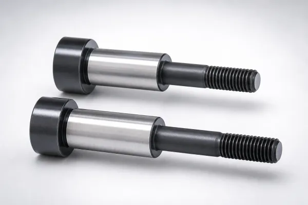
STBG Type Stopper Bolts for Three-Plate Mold Male Thread
STBG Type Stopper Bolts for Three-Plate Mold Male Thread help set and locate mold sections securely for repeatable op...
View Details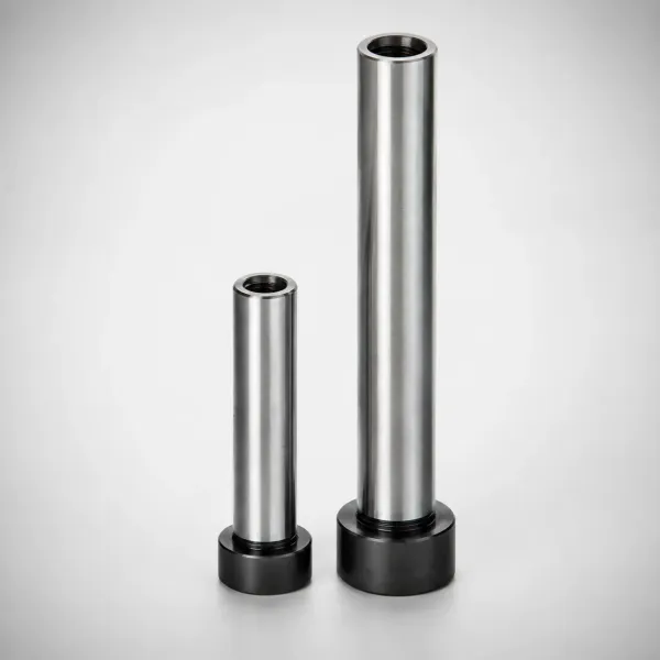
Female Thread Puller Bolts for Three-Plate Mold
Female thread puller bolts for three-plate molds by PBTN. Secure pulling engagement with reliable female thread desig...
View Details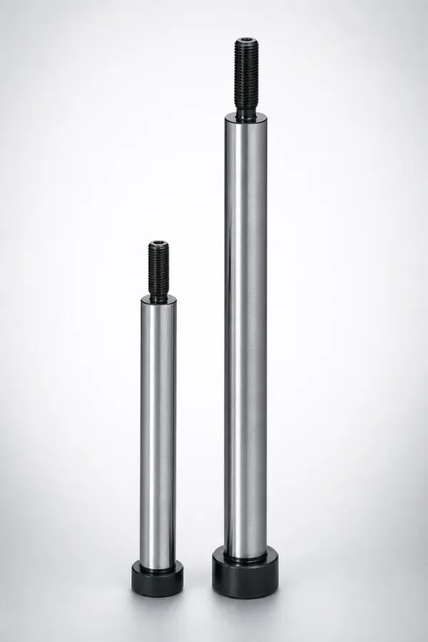
Puller Bolts for Three-Plate Mold - Male Thread
Puller Bolts for Three-Plate Mold - Male Thread provide secure tension adjustment, precise alignment, and pulling for...
View Details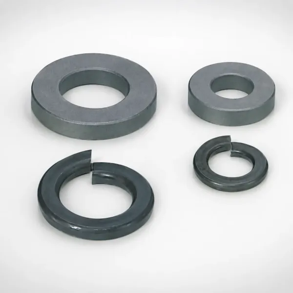
PBC Type Puller Bolt Collars Covers for Three-Plate Mold
Puller bolt collars covers for three-plate mold, type PBC. Protect and align puller bolts during assembly for stable ...
View Details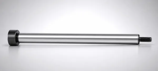
Puller Bolts for Three-Plate Mold - Male Thread, Short Tip
Puller Bolts for Three-Plate Mold - Male Thread, Short Tip for secure fastening and easy assembly/disassembly in thre...
View DetailsStopper Bolts vs Puller Bolts — How to Choose
Stopper bolts and puller bolts serve opposite roles in three-plate mold opening. Use this comparison to select the right type:
| Criteria | Stopper Bolts | Puller Bolts — Female Thread | Puller Bolts — Male Thread | Puller Bolts — Male, Short Tip |
|---|---|---|---|---|
| Function | Limits plate travel (hard stop) | Pulls plate apart (threaded socket) | Pulls plate apart (stud direct) | Pulls plate apart (reduced projection) |
| Thread Type | Male thread (bolt body) | Female thread socket at tip | Male thread stud at tip | Male thread, shortened stud |
| Installation | Thread into one plate; head contacts adjacent plate | Install bolt in plate A; separate screw from plate B engages socket | Thread stud directly into plate B | Thread short stud into plate B |
| Adjustability | Fixed by bolt length | High — adjust screw depth to fine-tune pull distance | Medium — fixed by thread engagement | Low — shortest engagement |
| Space Requirement | Standard | Largest (socket + screw) | Standard | Smallest |
| Best For | Defining stop positions at every parting line | Primary puller bolt, easy adjustment | Compact designs, limited access | Shallow plates, tight spaces |
Selection guide: Most three-plate molds use stopper bolts AND puller bolts together — stoppers define where plates stop, pullers provide the separation force. For a complete walkthrough, see our What Is the Difference Between Stopper Bolts and Puller Bolts in Three-Plate Molds.
How Stopper and Puller Bolts Work in Three-Plate Molds
Three-Plate Mold Opening Sequence
A three-plate mold has three major plates: the runner plate (A), cavity plate (B), and core plate (C). During opening, the A-B parting line (runner separation) must open first, then the B-C parting line (main parting). Stopper bolts are installed between plates to define the maximum travel at each parting line. The stopper bolt length at A-B is set shorter than at B-C, ensuring A-B reaches its stop position first, at which point the opening force transfers to B-C.
Puller Bolt Mechanics
Puller bolts are threaded fasteners that mechanically connect two plates across a parting line. As the mold opens, the puller bolt transfers the opening force from the driven plate to the pulled plate, ensuring the pulled plate separates from its adjacent surface. The bolt's thread engagement defines the pull distance. Female thread puller bolts offer adjustability — turning the engagement screw changes the pull length without replacing the bolt.
Collar Function
Puller bolt collars act as precision spacers between plates. When the mold is fully closed, the collar contacts both plate faces, defining the minimum plate gap. This prevents over-compression of O-rings, springs, or other compliant elements between plates. Collar height must be precisely ground to match the design plate gap.
Technical deep-dive: For detailed force diagrams and sequence timing, see our How Stopper Bolts and Puller Bolts Control Plate Separation Sequence.
Bolt & Collar Pairing Reference
Puller bolts and collars are designed to work together. Match by shaft diameter:
Puller Bolt (any thread type)
Select female/male thread based on adjustability needs. Choose shaft diameter by plate bore.
Puller Bolt Collar
Match collar inner diameter to puller bolt shaft. Collar height = design plate gap. Precision-ground to ±0.01 mm.
Where Stop & Puller Bolts Are Used
Three-Plate Mold Runner Separation
The most common application — stopper bolts define runner plate travel distance while puller bolts actively separate the runner plate from the cavity plate, ensuring clean runner detachment before main parting line opens.
Why it fits: Stopper bolts provide the precise stop position needed for runner vs. gate break timing. Puller bolts ensure the runner plate separates cleanly even with resin adhesion.
Multi-Parting-Line Stack Molds
Stack molds with 4+ plates require multiple stages of controlled separation. Each parting line needs its own set of stop positions to prevent simultaneous opening.
Why it fits: Multiple stopper bolts of different lengths create a cascading stop sequence. Puller bolts ensure each stage separates with positive force.
Prototype & Low-Volume Molds
Prototype molds that undergo frequent design changes need easily adjustable opening sequence control without permanent modifications.
Why it fits: Female thread puller bolts allow quick adjustment of pull distance. Stopper bolts can be replaced with different lengths as the design evolves.
Frequently Asked Questions
What is the role of stopper bolts vs puller bolts in three-plate mold operation?+
When should I use a female thread puller bolt vs a male thread puller bolt?+
What is a puller bolt collar and when is it needed?+
What thread sizes are available for three-plate mold stopper bolts?+
How do I determine the correct stopper bolt length for my mold design?+
Engineering Resources
What Is the Difference Between Stopper Bolts and Puller Bolts in Three-Plate Molds
Detailed comparison of function, installation, and selection criteria for stop and pull-back hardware.
How Stopper Bolts and Puller Bolts Control Plate Separation Sequence
Engineering analysis of force transfer, sequence timing, and length calculation for three-plate mold bolts.
Need a Custom Quote?
Specify your thread size, bolt length, thread type (female/male), and quantity. Custom lengths and collar heights available for precise plate spacing.