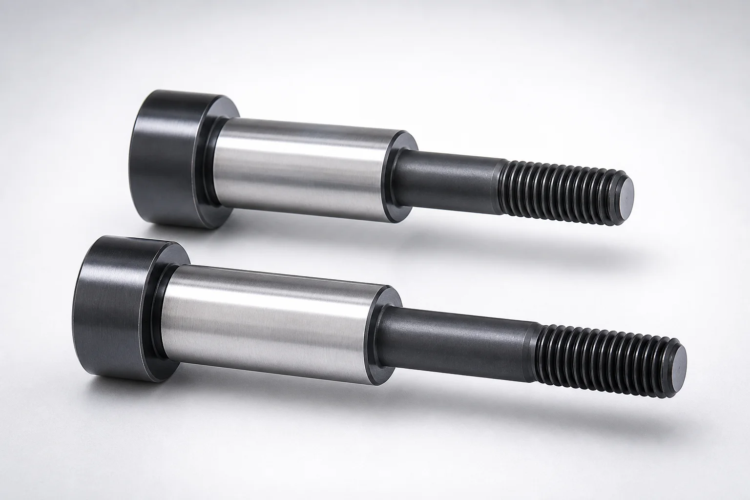
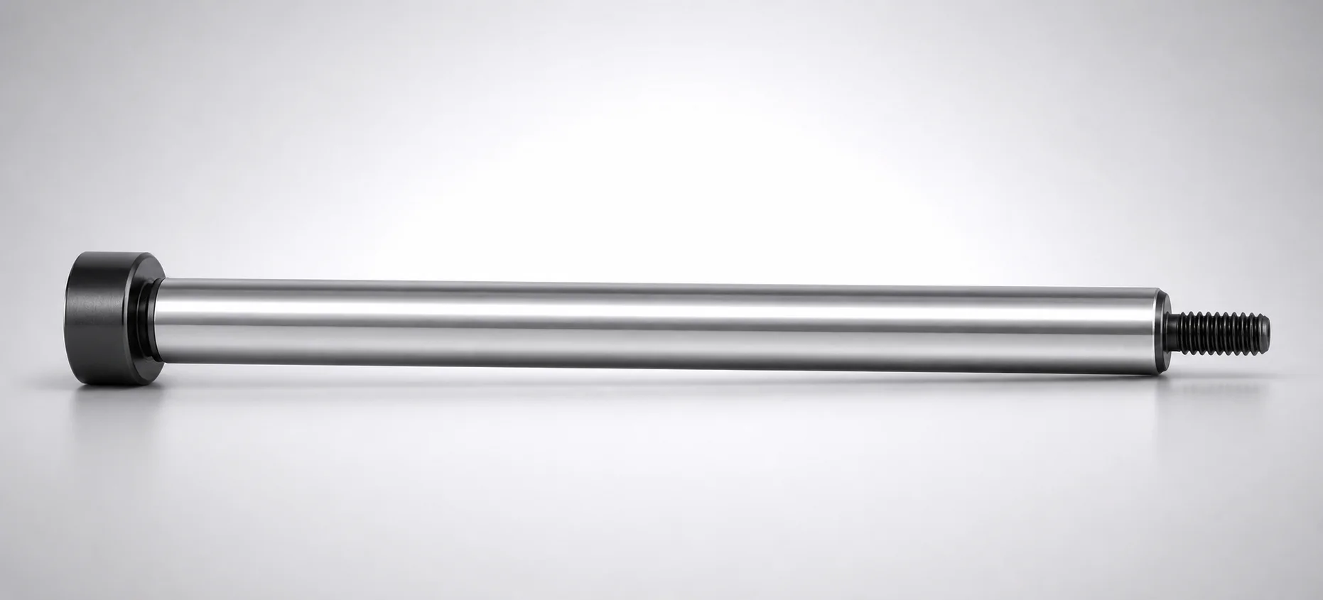
STBG Type Stopper Bolts for Three-Plate Mold Male Thread
Stopper bolts for three-plate mold (STBG type) with male thread provide stable positioning for mold sections during cycles. They are designed for reliable engagement to improve repeatability in production runs.
- Secure mold section contact using male thread stopper bolts
- STBG type design supports consistent fit and maintenance
- Threaded fastening improves assembly accuracy and serviceability
- Used in three-plate mold setups requiring positive stop and alignment
Specifications
102 configurations available
| D (Shaft Diameter) (mm) | Dimension L (mm) | E dimension (mm) | type |
|---|---|---|---|
| 10 | 10 | 19 | - |
| 10 | 10 | 24 | - |
| 10 | 15 | 19 | - |
| 10 | 15 | 24 | - |
| 10 | 15 | 29 | - |
| 10 | 20 | 19 | - |
| 10 | 20 | 24 | - |
| 10 | 20 | 29 | - |
| 10 | 20 | 34 | - |
| 13 | 10 | 22 | - |
| 13 | 10 | 27 | - |
| 13 | 15 | 22 | - |
| 13 | 15 | 27 | - |
| 13 | 15 | 32 | - |
| 13 | 15 | 37 | - |
| 13 | 20 | 22 | - |
| 13 | 20 | 27 | - |
| 13 | 20 | 32 | - |
| 13 | 20 | 37 | - |
| 13 | 20 | 42 | - |
| 13 | 25 | 27 | - |
| 13 | 25 | 32 | - |
| 13 | 25 | 37 | - |
| 13 | 25 | 42 | - |
| 13 | 30 | 27 | - |
| 13 | 30 | 32 | - |
| 13 | 30 | 37 | - |
| 13 | 30 | 42 | - |
| 13 | 30 | 47 | - |
| 13 | 35 | 37 | - |
| 13 | 35 | 42 | - |
| 13 | 35 | 47 | - |
| 16 | 10 | 30 | - |
| 16 | 10 | 35 | - |
| 16 | 15 | 30 | - |
| 16 | 15 | 35 | - |
| 16 | 15 | 40 | - |
| 16 | 20 | 30 | - |
| 16 | 20 | 35 | - |
| 16 | 20 | 40 | - |
| 16 | 20 | 45 | - |
| 16 | 25 | 30 | - |
| 16 | 25 | 35 | - |
| 16 | 25 | 40 | - |
| 16 | 25 | 45 | - |
| 16 | 25 | 50 | - |
| 16 | 30 | 35 | - |
| 16 | 30 | 40 | - |
| 16 | 30 | 45 | - |
| 16 | 30 | 50 | - |
Product Guide
Application Scenarios+
In three-plate injection mold tooling, this style of stopper bolt is used to set and locate mold sections securely during opening/closing cycles. The male-thread engagement helps establish a consistent mechanical stop, reducing variation in alignment from one production run to the next.
- Automotive and appliance housings: used in three-plate molds where tight part-to-part positional repeatability is needed across high-cycle runs. Male-thread fastening supports controlled assembly and dependable stop contact.
- Electronics connector molds: supports stable core/cavity positioning when side loads and stripping forces can influence shut height. The STBG configuration is suited for repeatable fit and easier maintenance during service.
- General industrial cover molds: ideal where positive stop function and straightforward disassembly are required for mold cleaning or component replacement.
With available shaft diameters (D = 10–30 mm) and adjustable lengths (L = 10–50 mm), engineers can match the stopper geometry to the specific three-plate layout and spacing requirements.
Material & Process Details+
The provided dataset identifies this as an STBG type stopper bolt for three-plate molds with male thread, but does not specify the steel grade, hardness (HRC), or heat treatment state. Therefore, material property claims (e.g., “quenched and tempered,” nitriding, or a specific equivalent such as H13/AISI or M2/AISI) cannot be stated from the given information.
When selecting a stopper bolt material for mold-opening controllers, engineers typically balance wear resistance at the stop-contact surfaces against toughness to avoid chipping under repeated impact loads. If you confirm the supplier’s steel grade for series code 110200106150, it is possible to validate hardness and heat treatment requirements for your cycle rate and load profile.
- Compare candidate steels based on required stop-surface wear life vs. allowable deflection/toughness.
- Verify whether the bolt is supplied pre-hardened, or heat treated to a specific target hardness before installation.
Sizing & Selection Guide+
Select dimensions to ensure the stopper bolt creates a repeatable positive stop without binding during mold opening/closing. From the provided specifications, the available options are D = 10, 13, 16, 20, 25, 30 mm, L = 10–50 mm, and E = 19–80 mm.
- D (shaft diameter): choose based on the required strength and the clearance/fit at the mounting interface for the three-plate mold layout.
- L (length): set to achieve the intended engagement depth and stop contact positioning within the three-plate assembly envelope.
- E dimension: match to the spacing or functional offset specified in your mold-opening controller design so the stop engages at the correct point of travel.
Because tolerance ranges are not included in the provided data, confirm the allowable fit with your mold standard (thread engagement and assembly clearance). For male-thread stopper bolts, ensure the installed thread engagement is sufficient for the contact forces while avoiding over-constraining shut height.
Frequently Asked Questions
How do I choose the correct shaft diameter D for an STBG stopper bolt on a three-plate mold?+
What L (length) should I select so the stopper bolt provides a consistent positive stop?+
What does the E dimension (19–80 mm) represent in the stopper bolt selection for mold-opening controllers?+
Is this stopper bolt intended for positive stop and alignment in three-plate molds only?+
Do I need to consider material hardness or heat treatment for cycle life on the stopper bolt?+
Related Products
Need Custom Specifications?
Our engineering team can help with custom configurations, material selection, and volume pricing.