Support Pillars
Structural columns that prevent mold plate deflection under clamping force — round, stepped, and height-adjustable types for every mold base size.
Support Pillars Categories
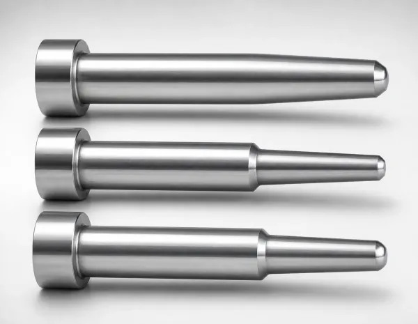
Round Support Pillars
Standard cylindrical pillars for general-purpose mold support. Hardened SUJ2 or S45C steel.
View Products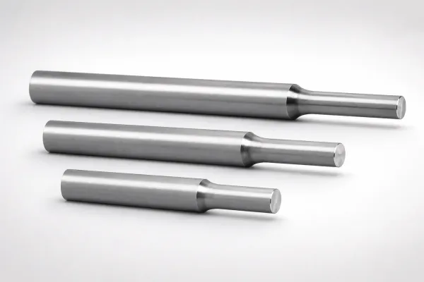
Stepped Support Pillars
Pillars with shoulder steps for positive plate location and simplified installation. Press-fit shoulder + clearance shaft.
View Products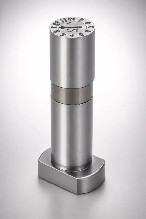
Adjustable Support Pillars
Height-adjustable pillars with threaded screw mechanism. Enables precise height setting without grinding.
View ProductsRound vs Stepped vs Adjustable — How to Choose
| Criteria | Round | Stepped | Adjustable |
|---|---|---|---|
| Installation | Press-fit or slip-fit into plate bore | Shoulder press-fits, shaft clears | Threaded into plate, height set by screw |
| Height Precision | Ground to ±0.01 mm | Ground to ±0.01 mm | Adjustable ±2 mm range |
| Load Capacity (Ø40) | ~80 kN | ~70 kN (reduced by step) | ~60 kN (screw joint limit) |
| Best For | Standard molds, high-tonnage | Molds needing positive location | Prototype molds, frequent changes |
| Cost | $ | $$ | $$$ |
Support Pillar Specification Quick Reference
Match pillar diameter and quantity to your mold base size and clamping tonnage.
| Mold Base Size (mm) | Min. Pillar Diameter | Min. Quantity | Max. Clamping (tons) |
|---|---|---|---|
| 250 × 250 | Ø20 | 4 | 100 |
| 400 × 400 | Ø30 | 4 | 300 |
| 600 × 600 | Ø40 | 4-6 | 500 |
| 800 × 800 | Ø50 | 6-8 | 800 |
How Support Pillars Prevent Plate Deflection
Under clamping force, the mold's support plate acts as a beam loaded in the center. Without support pillars, the plate deflects toward the ejector space — typically 0.02–0.10 mm for a 500-ton mold with a 600 × 600 mm plate. This deflection transmits directly to the cavity, causing flash at the parting line and dimensional variation in the molded part.
Support pillars placed between the support plate and the clamping plate provide direct load paths that bypass the ejector space. The rule of thumb is: pillar centers should be no more than 200 mm apart, and total pillar cross-section should support ≥ 120% of the clamping force. For example, four Ø40 mm pillars (80 kN each = 320 kN total) support up to approximately 32 tons — sufficient for a small mold but insufficient for a 100-ton press.
Learn more: For detailed technical guidance, see How to Calculate Support Pillar Load Capacity for Injection Molds.
About Support Pillars
Support pillars are hardened steel columns positioned between the mold support plate and the clamping plate. They prevent the support plate from deflecting into the ejector space under clamping load, which would otherwise cause cavity flash and part dimensional variation. Round pillars are the standard choice for high-tonnage production molds. Stepped pillars offer self-locating installation. Adjustable pillars allow height fine-tuning for prototype and frequent-changeover applications.
Frequently Asked Questions
What is the difference between round, stepped, and adjustable support pillars?+
How do I calculate the required number and size of support pillars for my mold?+
What load capacity do support pillars provide?+
Are support pillars hardened or case-hardened?+
Engineering Resources
Round vs Stepped vs Adjustable Support Pillars — How to Choose
Comparison of pillar types by load capacity, installation method, and application suitability.
How to Calculate Support Pillar Load Capacity for Injection Molds
Engineering formulas and reference tables for pillar sizing based on mold base size and clamping tonnage.
Need Custom Support Pillars?
Precision support pillars manufactured to JIS and DIN standards. MOQ 1 piece.