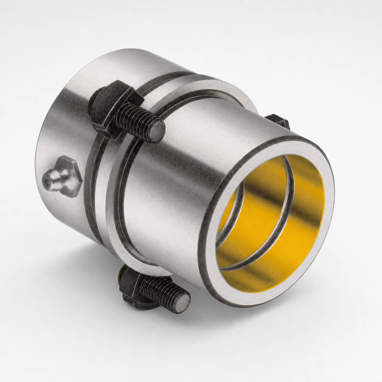
Wring Fit Shoulder Bushings - Inch
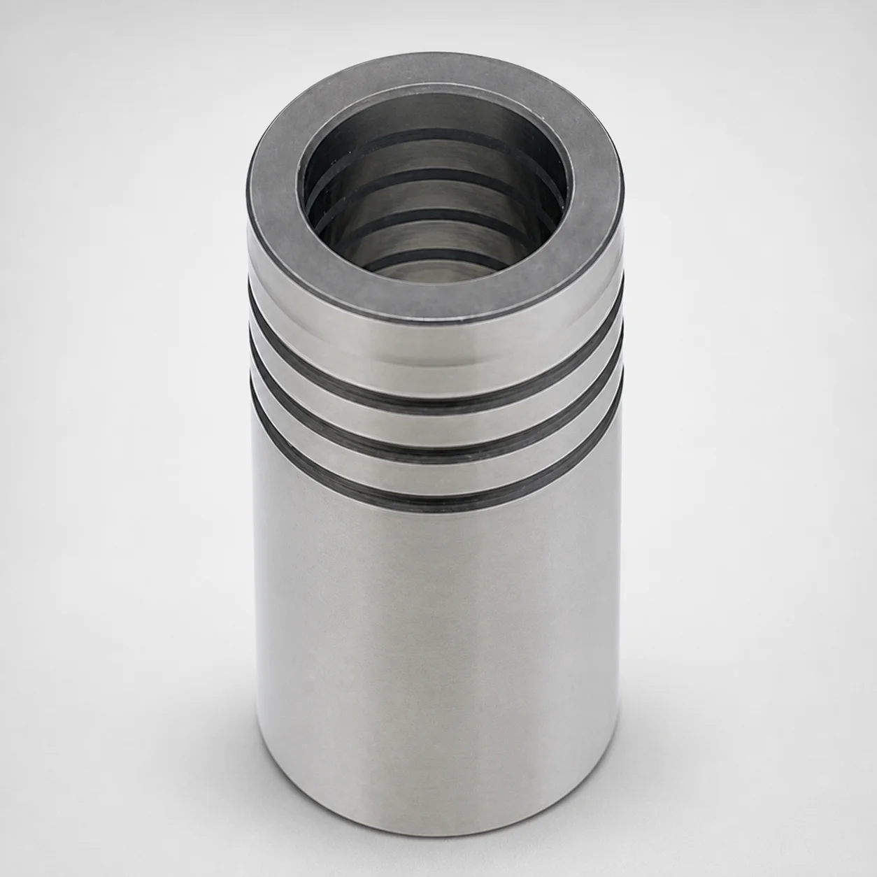
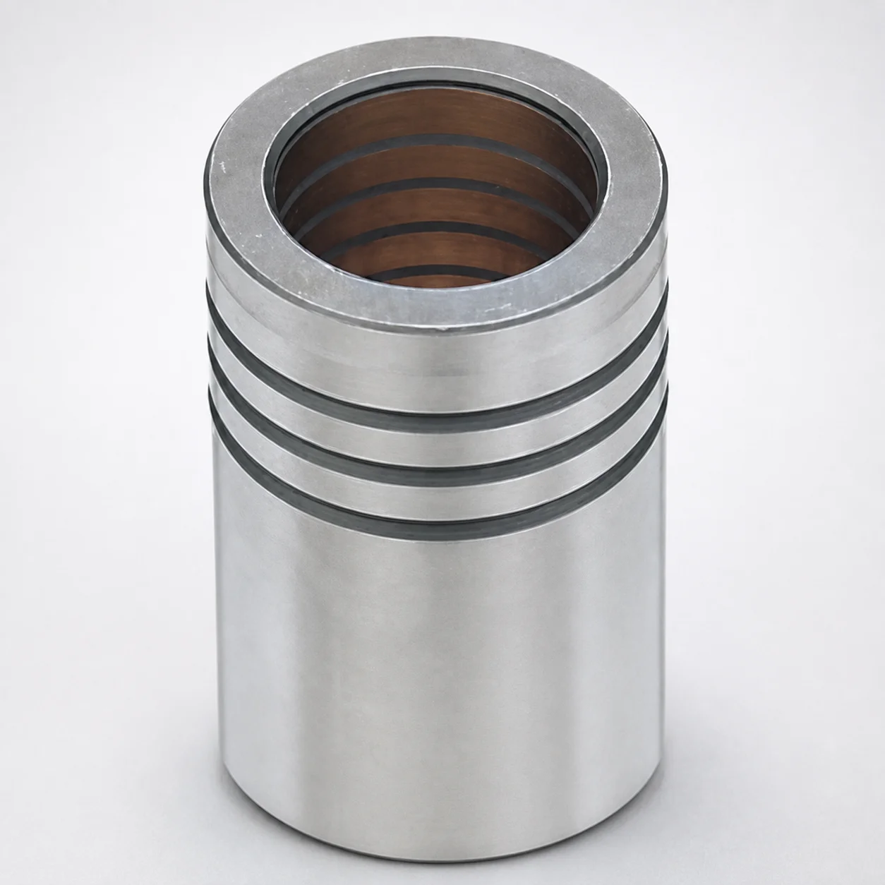
Wring Fit Shoulder Bushings - Inch (plain guide) from Lamina are designed to improve die set precision and guide stability. The wring-fit style supports smooth operation with convenient mounting in assembly workflows.
- Wring-fit shoulder geometry for consistent alignment in die sets
- Options in copper alloy or steel for durability and wear resistance
- Plain guide design promotes stable, low-friction movement under load
- Suitable for die applications where repeatable fit and easy installation matter
Specifications
135 configurations available
| Bushing Type | d (Bushing inner diameter) (in) | D2 (Outer diameter) (in) | L (Length) (in) | Type | Ground / Unground | Class |
|---|---|---|---|---|---|---|
| [Copper alloy] Bronze plated | 1 | 1.515 | 3.125 | Bronze plated | Unground | 1 |
| [Copper alloy] Bronze plated | 1 | 1.515 | 2.125 | Bronze plated | Unground | 1 |
| [Copper alloy] Bronze | 1 | 1.515 | 2.125 | Solid bronze | Unground | 1 |
| [Copper alloy] Bronze plated | 1-1/4 | 1.765 | 3.625 | Bronze plated | Unground | 1 |
| [Copper alloy] Bronze plated | 1-1/4 | 1.765 | 2.625 | Bronze plated | Unground | 1 |
| [Copper alloy] Bronze | 1-1/4 | 1.765 | 2.625 | Solid bronze | Unground | 1 |
| [Copper alloy] Bronze plated | 1-1/2 | 2.015 | 3.875 | Bronze plated | Unground | 1 |
| [Copper alloy] Bronze plated | 1-1/2 | 2.015 | 2.875 | Bronze plated | Unground | 1 |
| [Copper alloy] Bronze | 1-1/2 | 2.015 | 2.875 | Solid bronze | Unground | 1 |
| [Copper alloy] Bronze plated | 1-3/4 | 2.265 | 4.125 | Bronze plated | Unground | 1 |
| [Copper alloy] Bronze plated | 1-3/4 | 2.265 | 3.125 | Bronze plated | Unground | 1 |
| [Copper alloy] Bronze | 1-3/4 | 2.265 | 3.125 | Solid bronze | Unground | 1 |
| [Copper alloy] Bronze plated | 2 | 2.515 | 4.375 | Bronze plated | Unground | 1 |
| [Copper alloy] Bronze plated | 2 | 2.515 | 3.375 | Bronze plated | Unground | 1 |
| [Copper alloy] Bronze | 2 | 2.515 | 3.375 | Solid bronze | Unground | 1 |
| [Copper alloy] Bronze plated | 2-1/2 | 3.015 | 3.875 | Bronze plated | Unground | 1 |
| [Copper alloy] Bronze | 2-1/2 | 3.015 | 3.875 | Solid bronze | Unground | 1 |
| [Copper alloy] Bronze plated | 3 | 3.64 | 3.875 | Bronze plated | Unground | 1 |
| [Copper alloy] Bronze | 3 | 3.64 | 3.875 | Solid bronze | Unground | 1 |
| [Copper alloy] Bronze plated | 3/4 | 1.14 | 2.063 | Bronze plated | Unground | 1 |
| [Copper alloy] Bronze | 3/4 | 1.14 | 2.063 | Solid bronze | Unground | 1 |
| [Copper alloy] Bronze plated | 7/8 | 1.39 | 2.125 | Bronze plated | Unground | 1 |
| [Copper alloy] Bronze | 7/8 | 1.39 | 2.125 | Solid bronze | Unground | 1 |
| [Copper alloy] Bronze plated | 1 | 1.515 | 3.125 | Bronze plated | Unground | 2 |
| [Copper alloy] Bronze plated | 1 | 1.515 | 2.125 | Bronze plated | Unground | 2 |
| [Copper alloy] Bronze | 1 | 1.515 | 2.125 | Solid bronze | Unground | 2 |
| Steel | 1 | 1.515 | 2.125 | Solid steel | Unground | 2 |
| Steel | 1 | 1.515 | 2.875 | Solid steel | Unground | 2 |
| [Copper alloy] Bronze plated | 1-1/4 | 1.765 | 3.625 | Bronze plated | Unground | 2 |
| [Copper alloy] Bronze plated | 1-1/4 | 1.765 | 2.625 | Bronze plated | Unground | 2 |
| [Copper alloy] Bronze | 1-1/4 | 1.765 | 2.625 | Solid bronze | Unground | 2 |
| Steel | 1-1/4 | 1.765 | 2.625 | Solid steel | Unground | 2 |
| Steel | 1-1/4 | 1.765 | 3.125 | Solid steel | Unground | 2 |
| [Copper alloy] Bronze plated | 1-1/2 | 2.015 | 3.875 | Bronze plated | Unground | 2 |
| [Copper alloy] Bronze plated | 1-1/2 | 2.015 | 2.875 | Bronze plated | Unground | 2 |
| [Copper alloy] Bronze | 1-1/2 | 2.015 | 2.875 | Solid bronze | Unground | 2 |
| Steel | 1-1/2 | 2.015 | 2.875 | Solid steel | Unground | 2 |
| Steel | 1-1/2 | 2.015 | 3.375 | Solid steel | Unground | 2 |
| [Copper alloy] Bronze plated | 1-3/4 | 2.265 | 4.125 | Bronze plated | Unground | 2 |
| [Copper alloy] Bronze plated | 1-3/4 | 2.265 | 3.125 | Bronze plated | Unground | 2 |
| [Copper alloy] Bronze | 1-3/4 | 2.265 | 3.125 | Solid bronze | Unground | 2 |
| Steel | 1-3/4 | 2.265 | 3.125 | Solid steel | Unground | 2 |
| Steel | 1-3/4 | 2.265 | 3.625 | Solid steel | Unground | 2 |
| [Copper alloy] Bronze plated | 2 | 2.515 | 4.375 | Bronze plated | Unground | 2 |
| [Copper alloy] Bronze plated | 2 | 2.515 | 3.375 | Bronze plated | Unground | 2 |
| [Copper alloy] Bronze | 2 | 2.515 | 3.375 | Solid bronze | Unground | 2 |
| Steel | 2 | 2.515 | 3.375 | Solid steel | Unground | 2 |
| Steel | 2 | 2.515 | 3.875 | Solid steel | Unground | 2 |
| [Copper alloy] Bronze plated | 2-1/2 | 3.015 | 3.875 | Bronze plated | Unground | 2 |
| [Copper alloy] Bronze | 2-1/2 | 3.015 | 3.875 | Solid bronze | Unground | 2 |
Product Guide
Application Scenarios+
These wring-fit shoulder bushings are used in leader-ejector and die set guide assemblies to maintain alignment between moving components. The wring-fit shoulder geometry helps establish repeatable coaxial positioning during setup, which is especially valuable where guide stability affects part quality.
- Automotive and industrial die sets: Install in die space leader systems to support smooth, low-friction movement of punches and carriers. The plain guide form and selectable bushing material help balance wear resistance with operating smoothness.
- Thermoforming and stamping tools: Use the unground or ground variants to match build-stage requirements. Ground options can support tighter fit during assembly, while unground options support on-tool or final fit strategies.
- General transfer and progression tooling: Choose steel for higher durability under heavier guide loads or copper alloys for stable sliding behavior where friction management is critical.
Select the class (1/2/3) based on the accuracy and fit repeatability required in your press or die-height workflow.
Material & Process Details+
This series is offered in three bushing material families: bronze plated copper alloy, copper alloy bronze (solid), and steel. Copper alloy options generally provide good sliding behavior for guide applications, while steel prioritizes durability and wear resistance under higher loads.
- Bronze plated: Combines a plated copper alloy surface with improved wear characteristics for smooth guide motion.
- Solid bronze: Uses a copper-alloy bulk for stable friction performance; suitable when consistent sliding is more critical than maximum hardness.
- Solid steel: Chosen where robustness and long-term guide life are needed.
Ground vs. unground versions indicate the machining state rather than a specified heat-treatment in the provided data. The product is configured by type (bronze plated, solid bronze, solid steel, or self-lubricating) and by class (1/2/3), which should be aligned to your wear and fit targets. If your design requires nitriding or specific heat-treatment, confirm the exact grade and processing with the supplier because it is not specified in the provided parameters.
Sizing & Selection Guide+
Correct selection starts by matching the inner diameter (d), outer diameter (D2), and length (L) to your guide components and housing bores. For this line, the available ranges are: d = 1 ~ 7 in, D2 = 1.125 ~ 3.64 in, and L = 2.063 ~ 4.375 in.
- Match d to the mating leader/shaft: Choose the bushing inner diameter so the leader slides with the intended clearance and stability for your die set motion.
- Match D2 to the bushing pocket: Use the outer diameter to fit the guide bore/shoulder recess in the die base or platen housing.
- Set L for proper bearing coverage: Length should cover the required guide travel zone while avoiding interference with adjacent components during open/close cycles.
Decide between ground and unground based on your assembly strategy. Also select Class 1/2/3 to align with required fit accuracy; tolerance details are not provided here, so verify the class-based tolerance specification for your drawing and supplier confirmation.
Frequently Asked Questions
Which material type should I choose—bronze plated, solid bronze, solid steel, or self-lubricating—for die set guide wear?+
How do I select the correct bushing size using d, D2, and L ranges?+
What is the practical difference between ground and unground options for fit in leader bushings?+
What does Class 1/2/3 mean for compatibility with die set tolerances?+
How does the wring-fit shoulder geometry affect alignment in die sets?+
Related Products
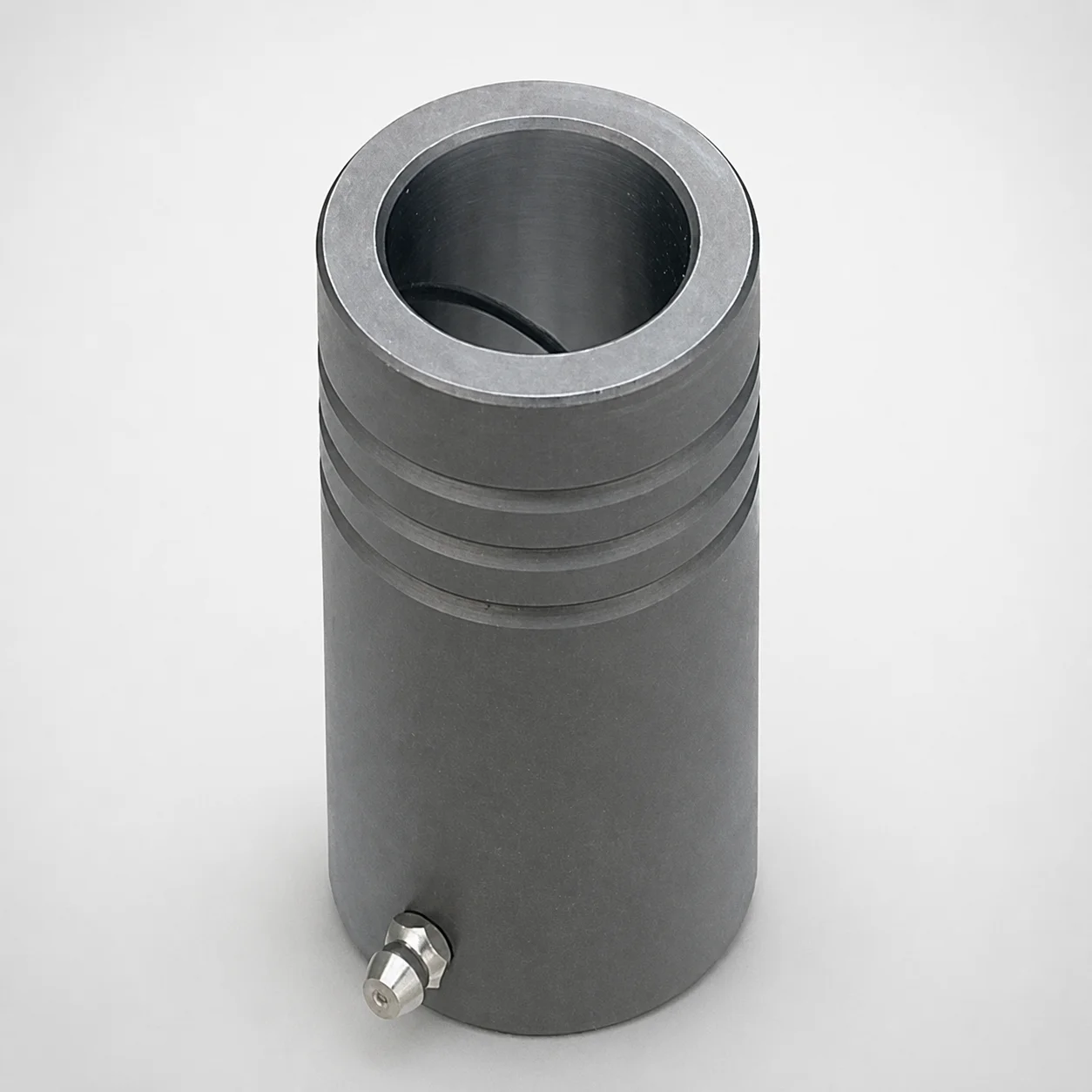
MDB Type Plain Guide Bushings for Die Sets (Oil Groove) Bonded by Devcon Adhesive
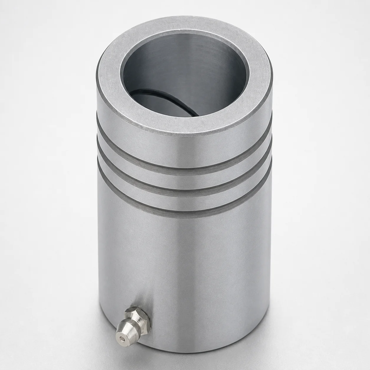
LDB Plain Guide Bushings for Die Sets
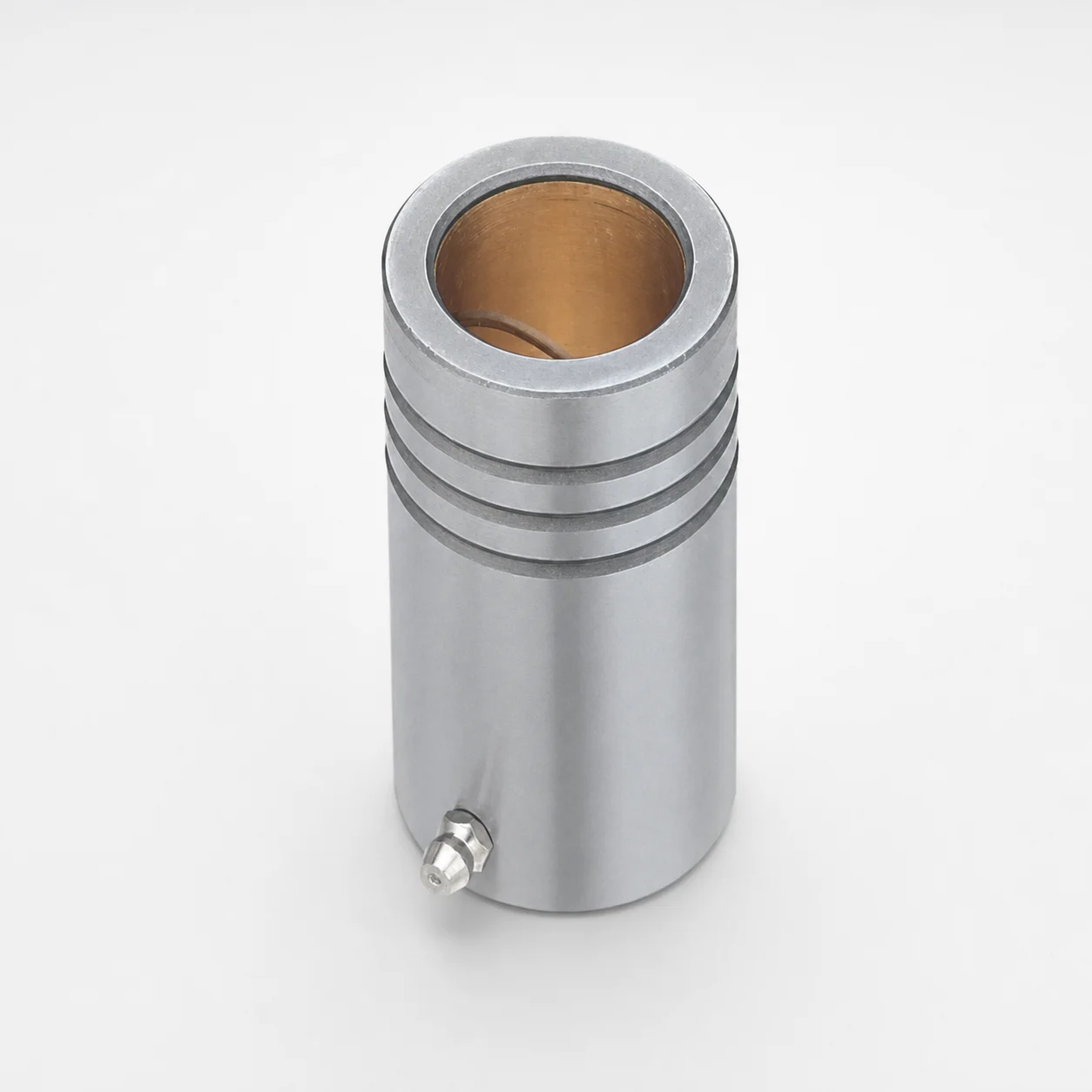
LFB Plain Guide Bushings for Die Sets with Oil Groove, Loctite Adhesive
DIN Standard Oil-Free Plain Guide Bushings LDBZ
LFBZ Plain Guide Bushings for Die Sets (Oil-Free Copper Alloy) Loctite Bonded
Plain Guide Bushings for Die Sets LDB
Need Custom Specifications?
Our engineering team can help with custom configurations, material selection, and volume pricing.