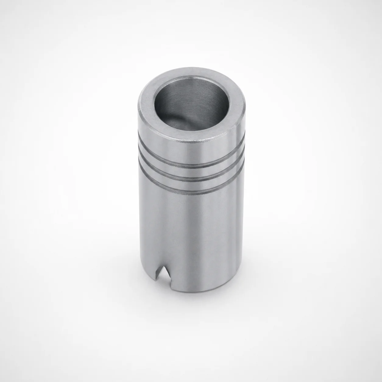
Plain Guide Bushings for Die Sets LDB
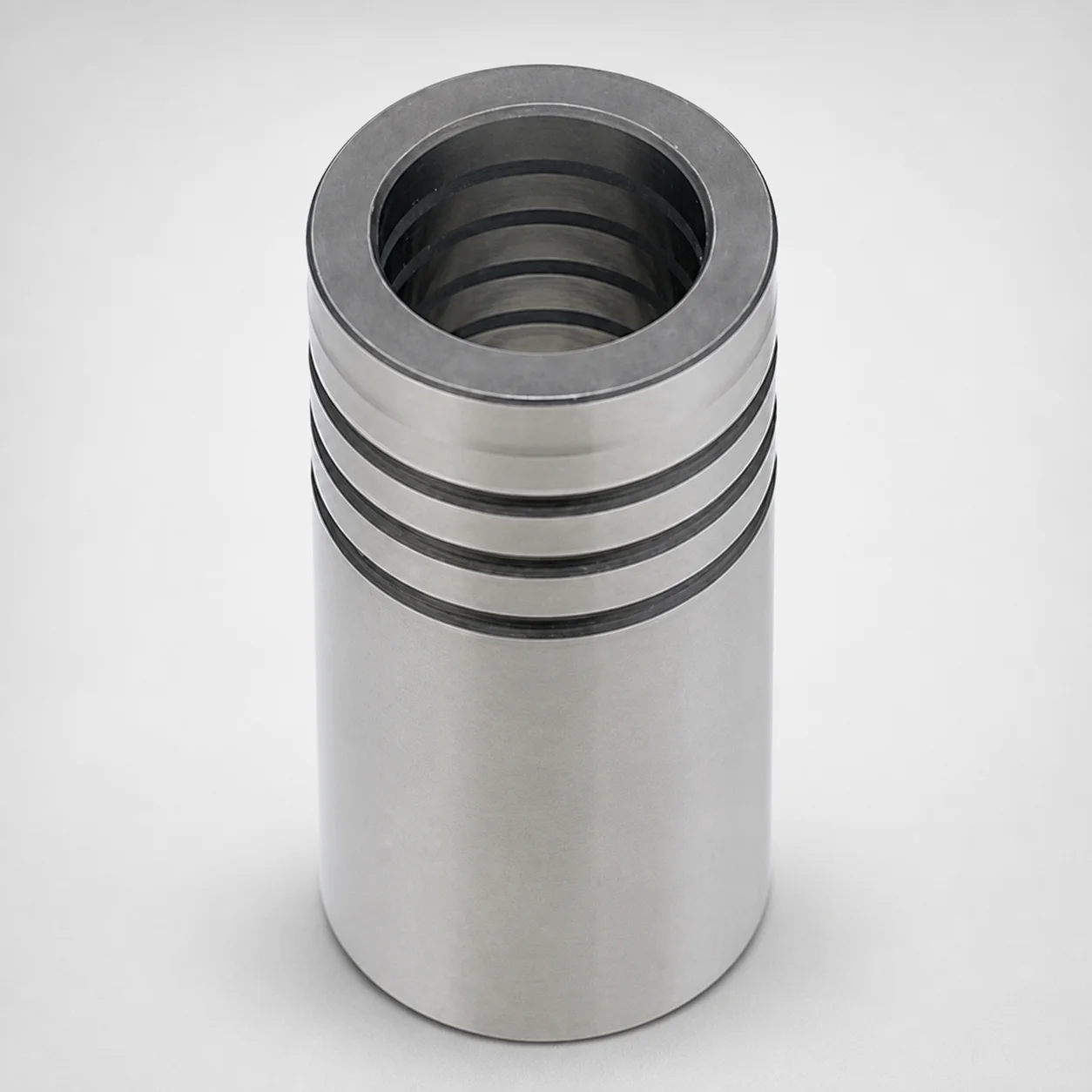
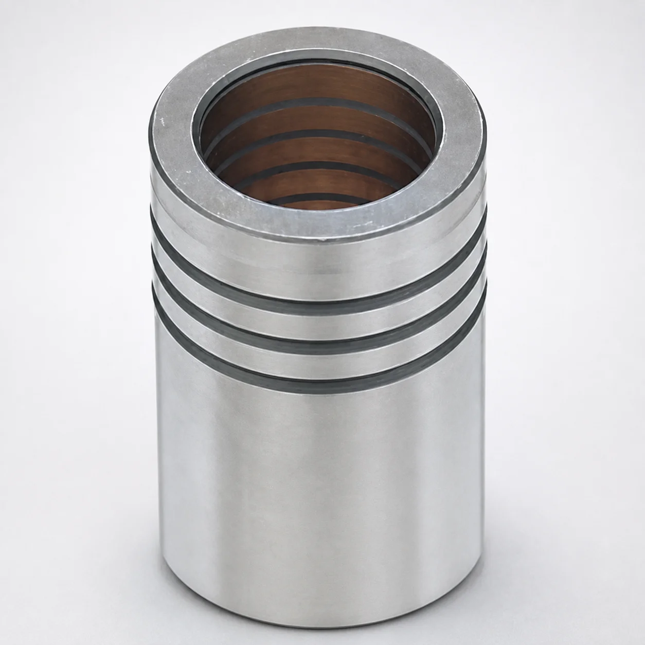
Plain guide bushings for die sets (LDB type) are designed for stable alignment in die assemblies, with an oil groove feature and Loctite adhesive bonding to help secure the bushing during operation.
- Plain guide bushing construction for consistent die-set positioning
- Oil groove type supports lubrication film retention for smooth sliding
- Loctite adhesive bonding method improves installation stability
- Use in die sets where long guide travel supports repeatable centering
Specifications
35 configurations available
| d (Bushing inner diameter) (mm) | L (Full Length) (mm) | LC (Full length alteration) (mm) | type |
|---|---|---|---|
| 20 | 50 | - | - |
| 20 | - | 25 ~ 49 | - |
| 20 | - | 51 ~ 120 | - |
| 22 | 50 ~ 60 | - | - |
| 22 | - | 25 ~ 49 | - |
| 22 | - | 51 ~ 59 | - |
| 22 | - | 61 ~ 120 | - |
| 25 | 60 ~ 80 | - | - |
| 25 | - | 30 ~ 59 | - |
| 25 | - | 61 ~ 79 | - |
| 25 | - | 81 ~ 120 | - |
| 28 | 60 ~ 80 | - | - |
| 28 | - | 30 ~ 59 | - |
| 28 | - | 61 ~ 79 | - |
| 28 | - | 81 ~ 150 | - |
| 32 | 80 ~ 100 | - | - |
| 32 | - | 40 ~ 79 | - |
| 32 | - | 81 ~ 99 | - |
| 32 | - | 101 ~ 150 | - |
| 38 | 80 ~ 100 | - | - |
| 38 | - | 40 ~ 79 | - |
| 38 | - | 81 ~ 99 | - |
| 38 | - | 101 ~ 180 | - |
| 45 | 100 ~ 120 | - | - |
| 45 | - | 50 ~ 99 | - |
| 45 | - | 101 ~ 119 | - |
| 45 | - | 121 ~ 180 | - |
| 50 | 100 ~ 120 | - | - |
| 50 | - | 50 ~ 99 | - |
| 50 | - | 101 ~ 119 | - |
| 50 | - | 121 ~ 200 | - |
| 60 | 100 ~ 120 | - | - |
| 60 | - | 50 ~ 99 | - |
| 60 | - | 101 ~ 119 | - |
| 60 | - | 121 ~ 200 | - |
Product Guide
Application Scenarios+
Plain guide bushings are used inside die sets to maintain die-to-die alignment during closing and repeatable leader motion. In automotive and industrial stamping tooling, they support long guide travel where stable centering and smooth sliding help reduce wear on mating leader elements.
The oil groove variant supports lubrication film retention, which is beneficial when cycles are frequent and boundary lubrication may occur at the contact interface. For assembly types that experience micro-misalignment from handling or repeated changeovers, the Loctite adhesive bonding approach improves installation stability so the bushing stays properly positioned in the die insert pocket.
- Automotive connector and bracket stamping die sets requiring consistent die positioning
- General-purpose progressive dies where long guide travel supports repeatable centering
- Die sets that benefit from adhesive-assisted retention to limit bushing shift
Material & Process Details+
The provided product metadata specifies the functional features (oil groove and Loctite adhesive bonding) and dimensional ranges, but it does not include the exact steel grade or heat-treatment state. Therefore, heat treatment, hardness (HRC), and wear/toughness trade-offs cannot be stated from the supplied data.
For proper materials selection in die-set guide applications, engineers typically match the bushing and mating leader materials to expected load, wear rate, and lubrication conditions. The oil groove feature is generally used to enhance lubrication retention at the sliding interface, improving wear behavior under cyclic movement.
- Material/grade: Not specified in the input data
- Hardness (HRC): Not specified in the input data
- Heat treatment state: Not specified in the input data
- Manufacturing emphasis: Oil-groove machining plus adhesive bonding for positional stability
Sizing & Selection Guide+
Select the bushing by matching the leader diameter and the die-set pocket geometry. The key inner diameter is d = 20 ~ 60 mm; choose the value that corresponds to the mating leader shaft diameter for proper guidance clearance.
Then select the full length based on the required guide engagement. Available full-length alteration ranges include L = 50, 50~60, 60~80, 80~100, 100~120 mm and LC = 25 ~ 121 mm. Use the length that provides adequate bearing/support along the leader during the full stroke.
- d (20–60 mm): match to leader shaft diameter class
- L (50–120 mm): match to required guide engagement length
- LC (25–121 mm): confirm it aligns with the designed alteration/step length in the die housing
Tolerance/fit considerations depend on the mating leader and the die bore tolerances, but the dimension ranges above define what sizes are available for selection. For adhesive-bonded retention, ensure the bushing seats consistently in the pocket so adhesive thickness and curing do not shift the guide axis.
Frequently Asked Questions
How do I choose the correct inner diameter (d) for mating leader shafts in LDB plain guide bushings?+
The bushing inner diameter is specified as d = 20 ~ 60 mm. Select the d value that matches the leader shaft diameter class used in your die set so the guide functions as intended over the full stroke.
If your leader diameter is near the boundary of a range, confirm your intended clearance/fit with your die designer’s tolerance stack and verify that adhesive bonding in the pocket does not introduce angular misalignment.
What do the available length ranges (L and LC) imply for guide engagement in die-set alignment?+
Full length alteration options are provided as L = 50, 50~60, 60~80, 80~100, 100~120 mm and LC = 25 ~ 121 mm. Use L to ensure sufficient guide contact length during die closing/opening, especially where long guide travel supports repeatable centering.
Confirm LC against your die insert/pocket geometry, since LC is the provided alteration/length-related dimension that must align with the designed housing features.
When should I use the oil groove feature in die sets using plain guide bushings?+
This variant includes an oil groove intended to support lubrication film retention for smooth sliding. Use it when your die set cycles are frequent or when boundary lubrication conditions are likely at the guide interface.
Oil groove retention can help maintain alignment consistency by reducing run-in wear and stabilizing the sliding behavior during repeated strokes.
How does Loctite adhesive bonding affect installation stability compared with friction-only retention?+
The design uses Loctite adhesive bonding to help secure the bushing during operation. This is particularly useful in die assemblies where repeated handling, changeovers, or micro-shifts can otherwise allow the bushing to migrate in its pocket.
For best results, the bushing should seat consistently in the die-set pocket so the bonding surface area remains stable and alignment is not disturbed during cure.
Can I specify material hardness or a specific steel grade from the provided LDB bushing metadata?+
No—your input data does not include a steel grade, hardness (HRC), or heat treatment state. It only provides functional features (oil groove and Loctite bonding) and dimensional ranges for d, L, and LC.
If you require a specific grade/heat treatment for wear and toughness targets, request the exact material specification associated with series code 110100161350.
Related Products
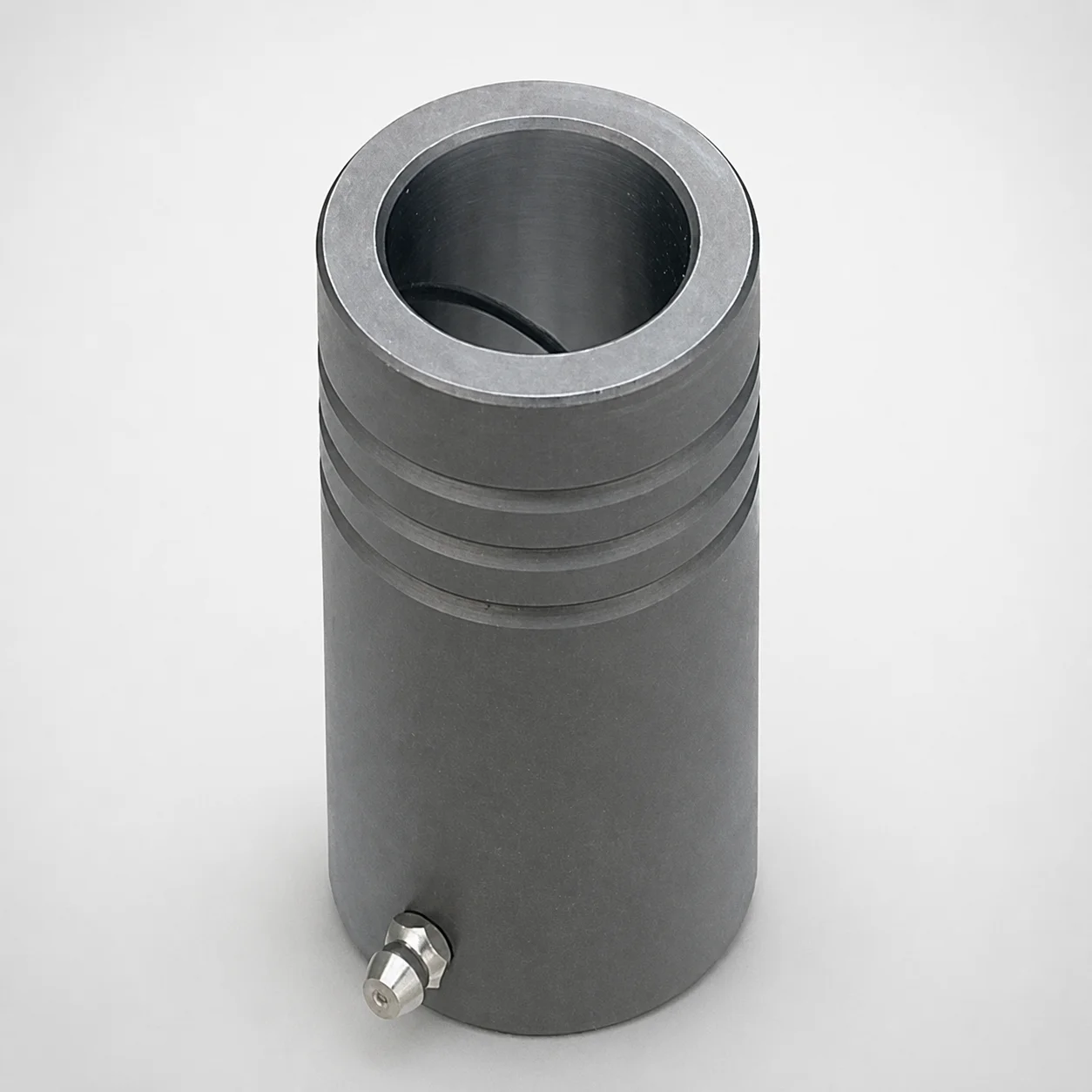
MDB Type Plain Guide Bushings for Die Sets (Oil Groove) Bonded by Devcon Adhesive
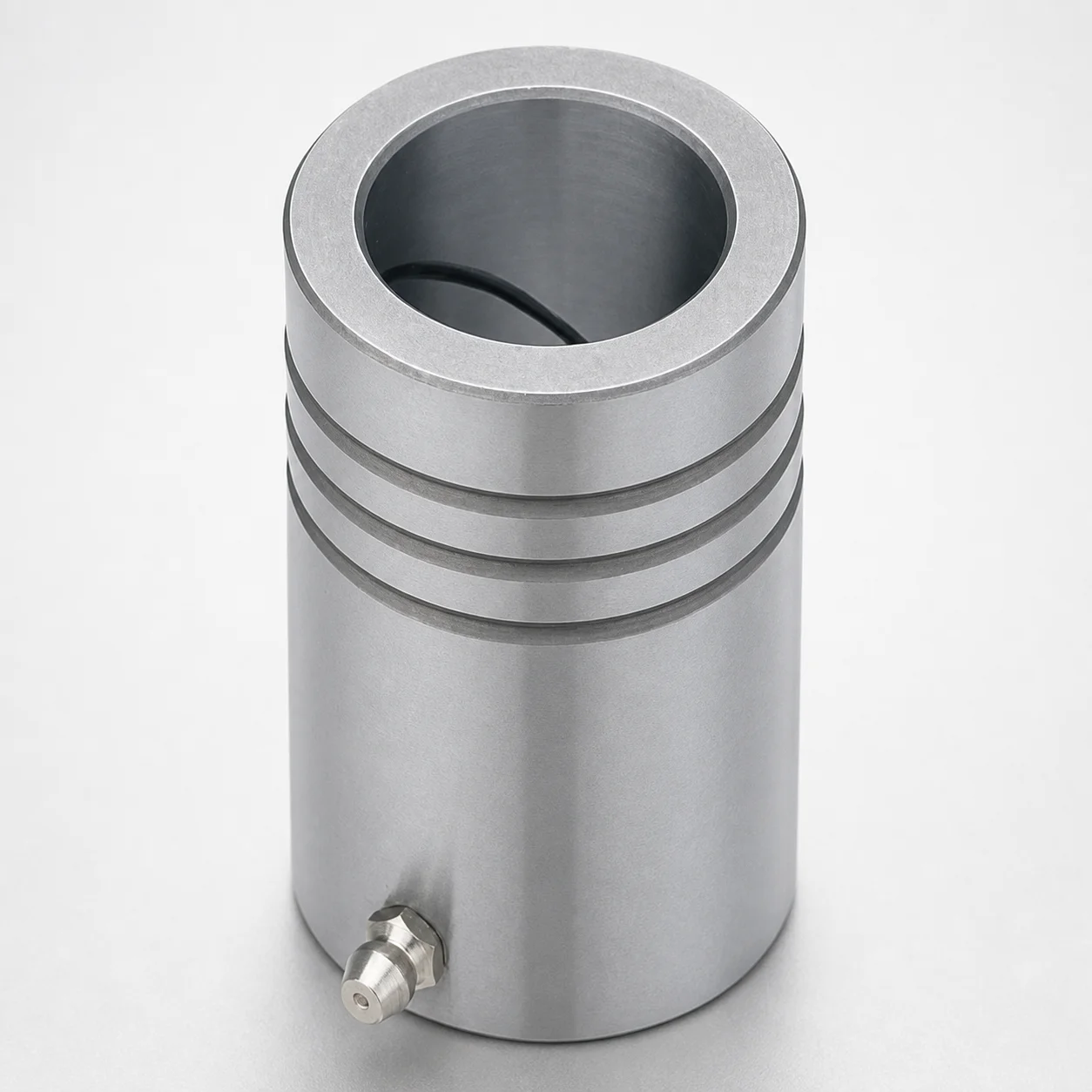
LDB Plain Guide Bushings for Die Sets
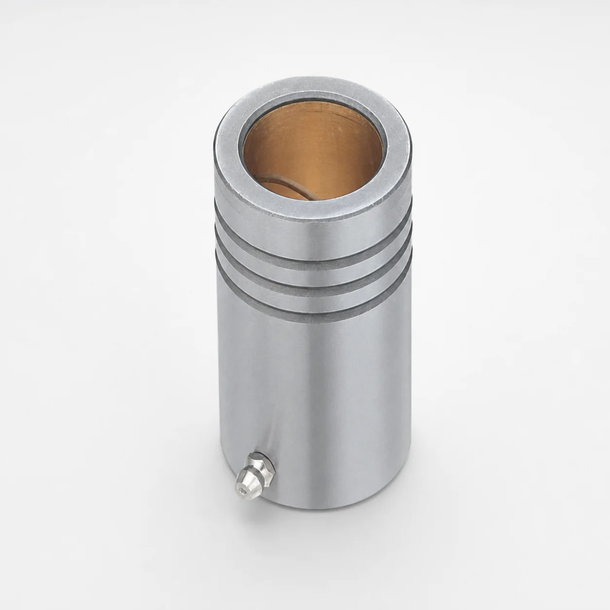
LFB Plain Guide Bushings for Die Sets with Oil Groove, Loctite Adhesive
DIN Standard Oil-Free Plain Guide Bushings LDBZ
LFBZ Plain Guide Bushings for Die Sets (Oil-Free Copper Alloy) Loctite Bonded
ISO 9448-6 Guide Bushings with Collar (Long)
Need Custom Specifications?
Our engineering team can help with custom configurations, material selection, and volume pricing.