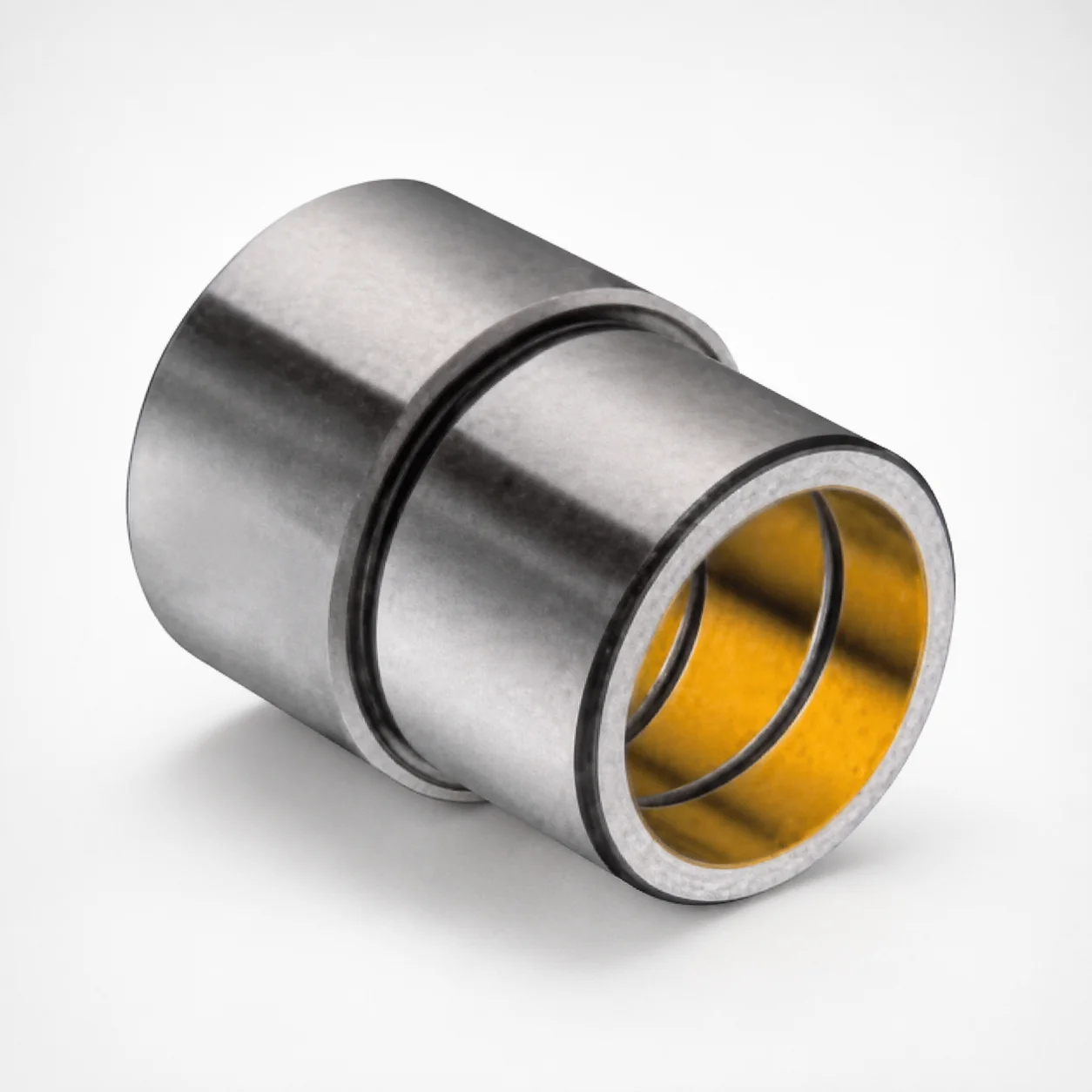
Plain Guide Bushings Pressed Fit Style Inch
Plain guide bushings pressed fit style inch (bronze plated copper alloy) are designed for die sets, providing stable positioning that minimizes lateral movement during operation and helps maintain precise alignment. Built for reliable wear reduction to support long service life in production tooling.
- Pressed fit style design improves dimensional stability under die load
- Bronze plated copper alloy construction supports consistent alignment and reduced wear
- Offers smooth, precise fit for stable operation across die set applications
- Inch series plain guide bushings for common die-set guidance requirements
Specifications
3 configurations available
| d (Bushing inner diameter) (in) | D2 (Outer diameter) (in) | L (Length) (in) |
|---|---|---|
| 1.0006 - 1.0003 | 1.5023 - 1.5018 | 2.5 |
| 1.2506 - 1.2503 | 1.7523 - 1.7518 | 2.688 |
| 1.5007 - 1.5004 | 2.0023 - 2.0018 | 2.938 |
Product Guide
Application Scenarios+
Pressed-fit plain guide bushings are used inside leader systems for precision alignment in progressive and transfer die sets. In automotive connector and terminal tooling, the bushing supports the leader components while maintaining stable guidance under repeated die opening/closing, helping minimize lateral drift and improving feature-to-feature consistency.
For appliance and industrial hardware forming dies, this inch-series bushing’s pressed fit helps lock alignment during high-cycle production. The bronze plated copper alloy construction is suited to guide wear conditions where smooth sliding and controlled wear are needed to preserve die geometry over time.
- Die sets for electrical/automotive components requiring tight positional repeatability
- Metal forming and assembly dies where long-running guidance stability reduces scrap
- Applications benefiting from stable fit without frequent adjustment
Material & Process Details+
This variant uses a bronze plated copper alloy for the bushing body. The copper alloy base provides good machinability and formability for accurate guide geometry, while the bronze plating is intended to improve surface wear behavior against the mating leader component.
Because the input data does not specify a specific steel grade or heat-treating method (e.g., quench & temper, nitriding) or provide hardness values in HRC, hardness and HRC-based trade-offs cannot be stated from the provided specifications.
- Wear resistance: Bronze plated sliding surface supports consistent guidance and reduced abrasive wear.
- Toughness vs. hardness trade-off: Not quantified in the supplied data; performance is driven by plated surface behavior.
- Heat treatment: Not specified; confirm with material certificate for any controlled treatment process.
Sizing & Selection Guide+
Select dimensions by matching the bushing’s inner diameter (d) to the leader diameter, and the outer diameter (D2) to the bore in the die set (or bushing housing). This pressed-fit style is intended to deliver positional stability, so dimensional matching is critical.
From the provided ranges, choose the closest available sizes for the required fit:
- d (in): 1.0006–1.0003, 1.2506–1.2503, 1.5007–1.5004
- D2 (in): 1.5023–1.5018, 1.7523–1.7518, 2.0023–2.0018
- L (in): 2.5, 2.688, 2.938
For guidance alignment, use the d range to target the leader diameter, then verify the housing bore matches the D2 size for pressed-fit engagement. Tolerance/fit should be confirmed against your die housing and leader manufacturing tolerances to ensure the intended interference without excessive stress.
Length L is fixed per variant (2.5, 2.688, or 2.938 in) and should be selected to cover the required guide travel and support length within the die.
Frequently Asked Questions
What leader inner diameter range (d) should I match for the pressed-fit bushing variants?+
How do I choose the correct outer diameter (D2) for the die housing bore?+
Which length (L) variants are available, and how should I align them with the guide engagement zone?+
What material finish or surface function does the bronze plated copper alloy provide for die alignment?+
Is there any specified heat treatment or hardness (HRC) for this guide bushing?+
Related Products
MDB Type Plain Guide Bushings for Die Sets (Oil Groove) Bonded by Devcon Adhesive
LDB Plain Guide Bushings for Die Sets
LFB Plain Guide Bushings for Die Sets with Oil Groove, Loctite Adhesive
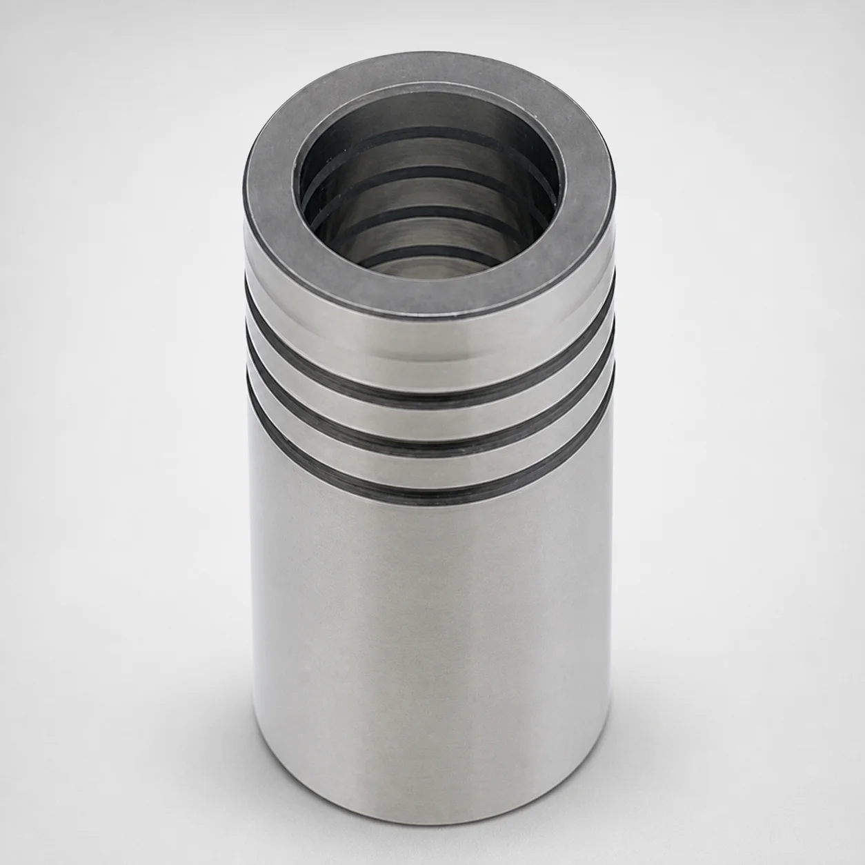
DIN Standard Oil-Free Plain Guide Bushings LDBZ
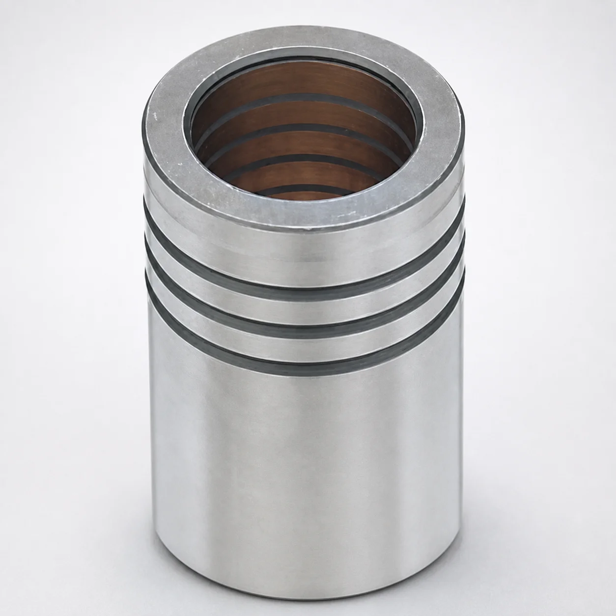
LFBZ Plain Guide Bushings for Die Sets (Oil-Free Copper Alloy) Loctite Bonded
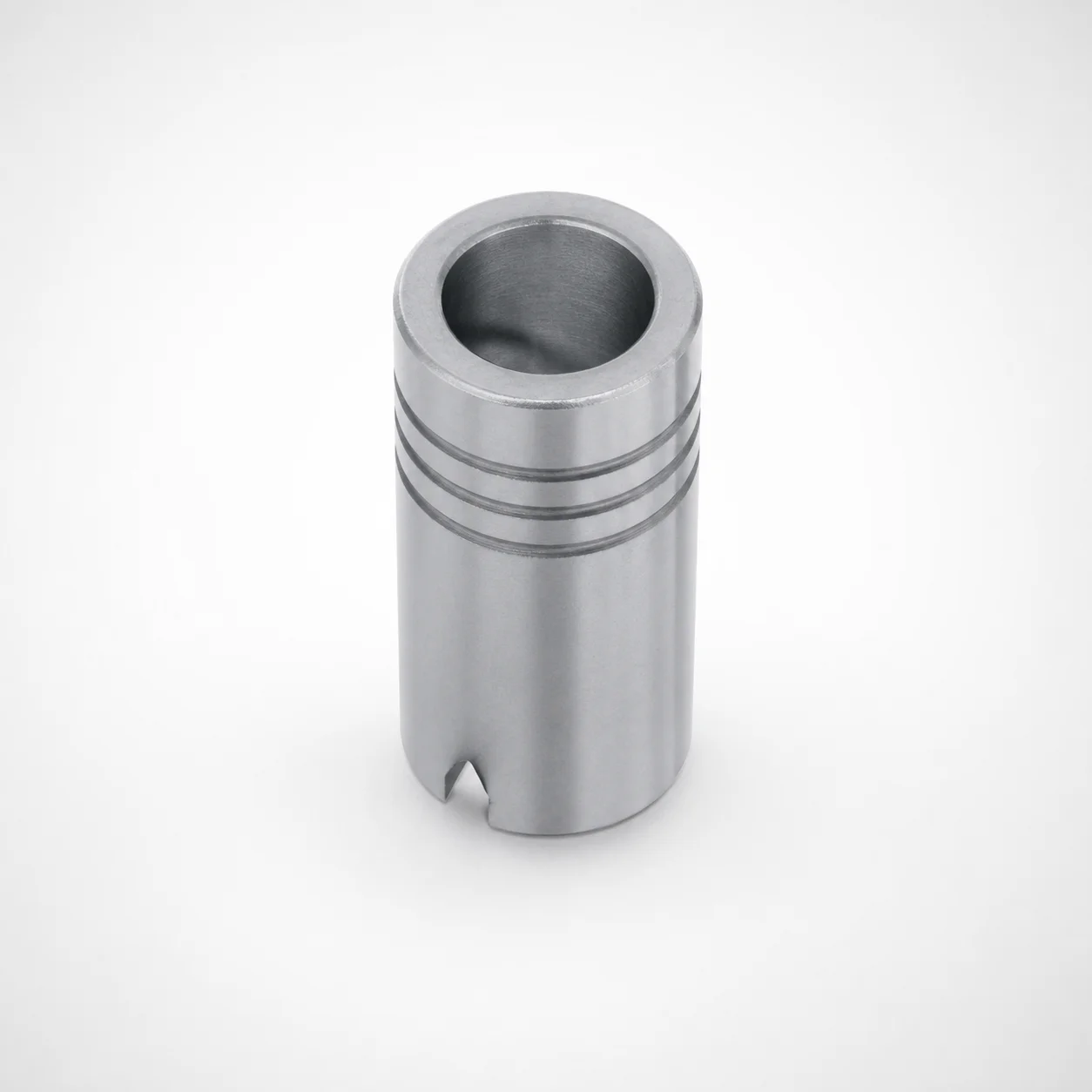
Plain Guide Bushings for Die Sets LDB
Need Custom Specifications?
Our engineering team can help with custom configurations, material selection, and volume pricing.