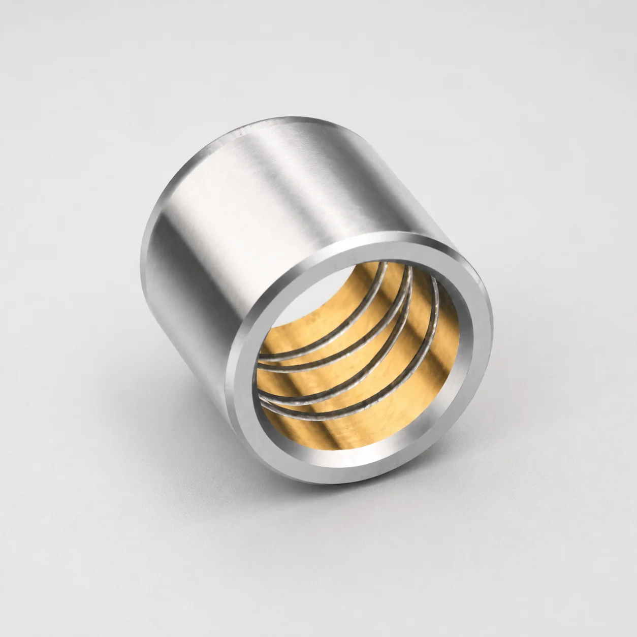
Inch Plain Guide Bushings (Bronze-Plated) Pressed Fit
Plain guide bushings (bronze-plated) for pressed fit applications in inch configurations. Built as a plain guide bushing only, with Loctite adhesive mounting to improve retention and positioning during operation.
- Plain guide bushing design supports straight alignment in die and slide setups
- Bronze-plated bushing surface helps reduce friction and manage wear over service cycles
- Loctite adhesive mounting complements the press fit for stable assembly retention
- Inch press-fit style suitable for engineers specifying precision bearing components
Specifications
12 configurations available
| d (Bushing inner diameter) (in) | D2 (Outer diameter) (in) | L (Length) (in) |
|---|---|---|
| 0.7502-0.7500 | 1.1272 - 1.1268 | 1-3/4 |
| 0.8752-0.8750 | 1.3772 - 1.3768 | 1-3/4 |
| 0.8752 - 0.8750 | 1.3772 - 1.3768 | 3 |
| 1.0002 - 1.0000 | 1.5022 - 1.5018 | 1-3/4 |
| 1.0002 - 1.0000 | 1.5022 - 1.5018 | 3 |
| 1.2502 - 1.2500 | 1.7522 - 1.7518 | 2 |
| 1.2512 - 1.2500 | 1.7522 - 1.7518 | 3 |
| 1.5002 - 1.5000 | 2.0022 - 2.0018 | 2 |
| 1.5002 - 1.5000 | 2.0022 - 2.0018 | 3 |
| 1.7502 - 1.7500 | 2.2522 - 2.2518 | 3 |
| 2.0002 - 2.0000 | 2.5022 - 2.5018 | 3 |
| 2.5002 - 2.5000 | 3.0022 - 3.0018 | 3 |
Product Guide
Application Scenarios+
Where it’s used: This inch-system plain guide bushing is commonly specified in leader/ejector tooling to maintain straight alignment between die and moving frames. The bronze-plated running surface is intended to reduce friction and slow wear during repeated open/close cycles.
Scenario 1—Automotive trim & connector housings: In injection molds with slide-driven mechanisms, pressed-fit guide bushings help keep the leader motion stable under high cycle loads. The Loctite adhesive mounting supports secure retention, reducing micro-movement that can otherwise lead to alignment drift.
Scenario 2—Appliance and industrial casings: For larger die sets where side loads are frequent, the plain guide geometry promotes consistent, parallel movement. The specified inner diameter range (d) and outer diameter range (D2) allow engineers to match alignment needs in inch tooling while keeping assembly repeatable.
Scenario 3—Medical device housings (small-scale alignment): In precision housings where part straightness is sensitive, the stable press-fit and wear-managed bronze surface support predictable guide performance over service cycles.
Material & Process Details+
Material behavior (bronze-plated): This bushing uses a bronze-plated surface to improve sliding performance. Bronze plating is selected to help manage friction and wear at the guide interface, supporting smoother motion and longer service intervals in repetitive mold cycles.
- Wear resistance vs. toughness: Bronze-plated running surfaces are optimized for low friction and wear, trading off against deeper bulk-hardness where extreme impact resistance is required.
- Heat treatment state: The provided specifications describe a bronze-plated guide bushing with Loctite adhesive mounting for retention; no specific quenched-and-tempered, nitrided, or HRC hardness value is provided in the available data.
- Process notes: The component is intended for pressed-fit installation, with the adhesive mounting reinforcing retention and positioning stability after assembly.
If you need an HRC target or a specific substrate grade (e.g., H13/M2 equivalents), share your drawing requirements so the correct material definition can be confirmed for your build.
Sizing & Selection Guide+
Step 1—Select by inner diameter (d): Choose the bushing inner diameter within 0.7502 ~ 2.5002 in to match the leader/guide shaft size used in your mold. A close match helps maintain proper guidance without excessive clearance.
Step 2—Match the outer diameter for the bore: Verify the press-fit seat diameter using the specified outer diameter D2 = 1.1272 ~ 3.0022 in. The selected D2 must correspond to the housing/bushing pocket size to achieve the intended press-fit retention.
Step 3—Confirm length (L): The available lengths are 1-3/4, 3, 2 in (discrete options). Pick the length that matches your mold’s guide engagement depth so the leader is supported over the required travel.
- Fit & tolerances: Because this is a pressed fit with Loctite adhesive mounting, you should coordinate tolerances between the bushing D2 and the pocket bore to avoid looseness or assembly interference.
- Configurable vs. fixed: d and D2 are selected within the given ranges, while L is limited to the listed discrete lengths.
Frequently Asked Questions
How do I choose the correct inner diameter d for this plain guide bushing in an inch leader system?+
What outer diameter D2 should I use to achieve the pressed-fit retention in the guide pocket?+
Which length options L are available, and how should I select engagement depth in the mold?+
Is bronze-plated surface performance appropriate for wear-critical injection cycles and side-loaded mechanisms?+
Does this variant include information on hardness (HRC) or specific steel substrate grade for wear/toughness requirements?+
Related Products
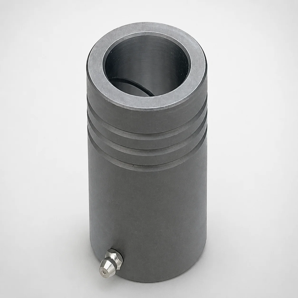
MDB Type Plain Guide Bushings for Die Sets (Oil Groove) Bonded by Devcon Adhesive
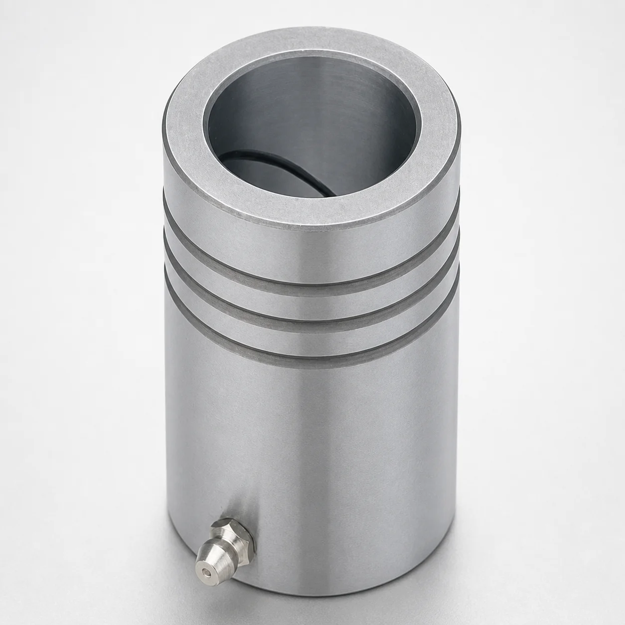
LDB Plain Guide Bushings for Die Sets
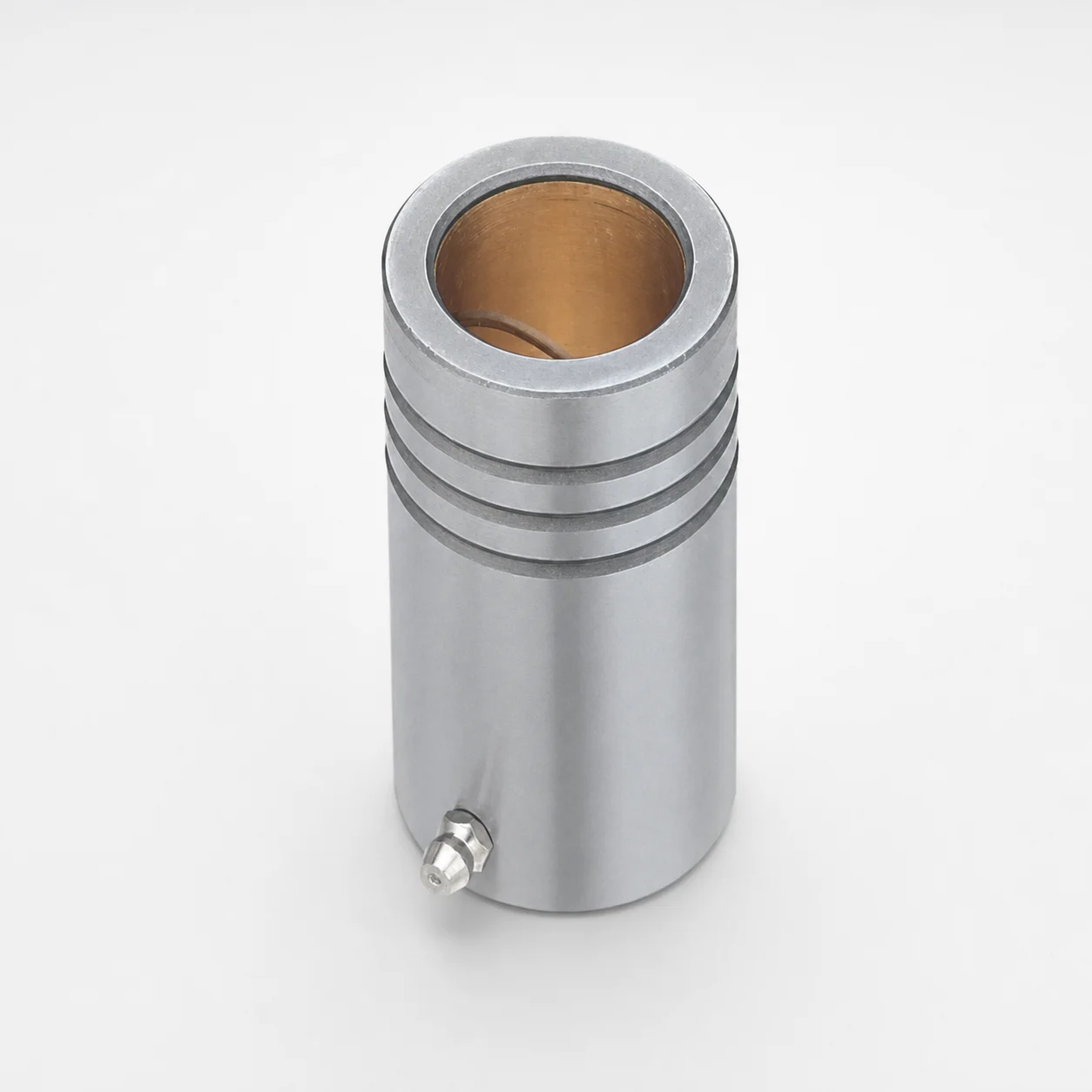
LFB Plain Guide Bushings for Die Sets with Oil Groove, Loctite Adhesive
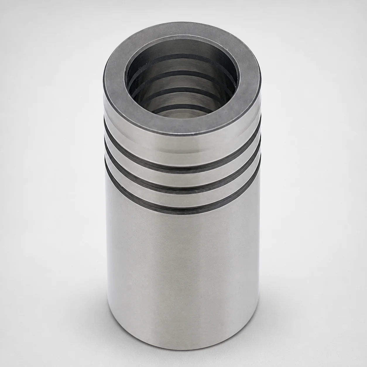
DIN Standard Oil-Free Plain Guide Bushings LDBZ
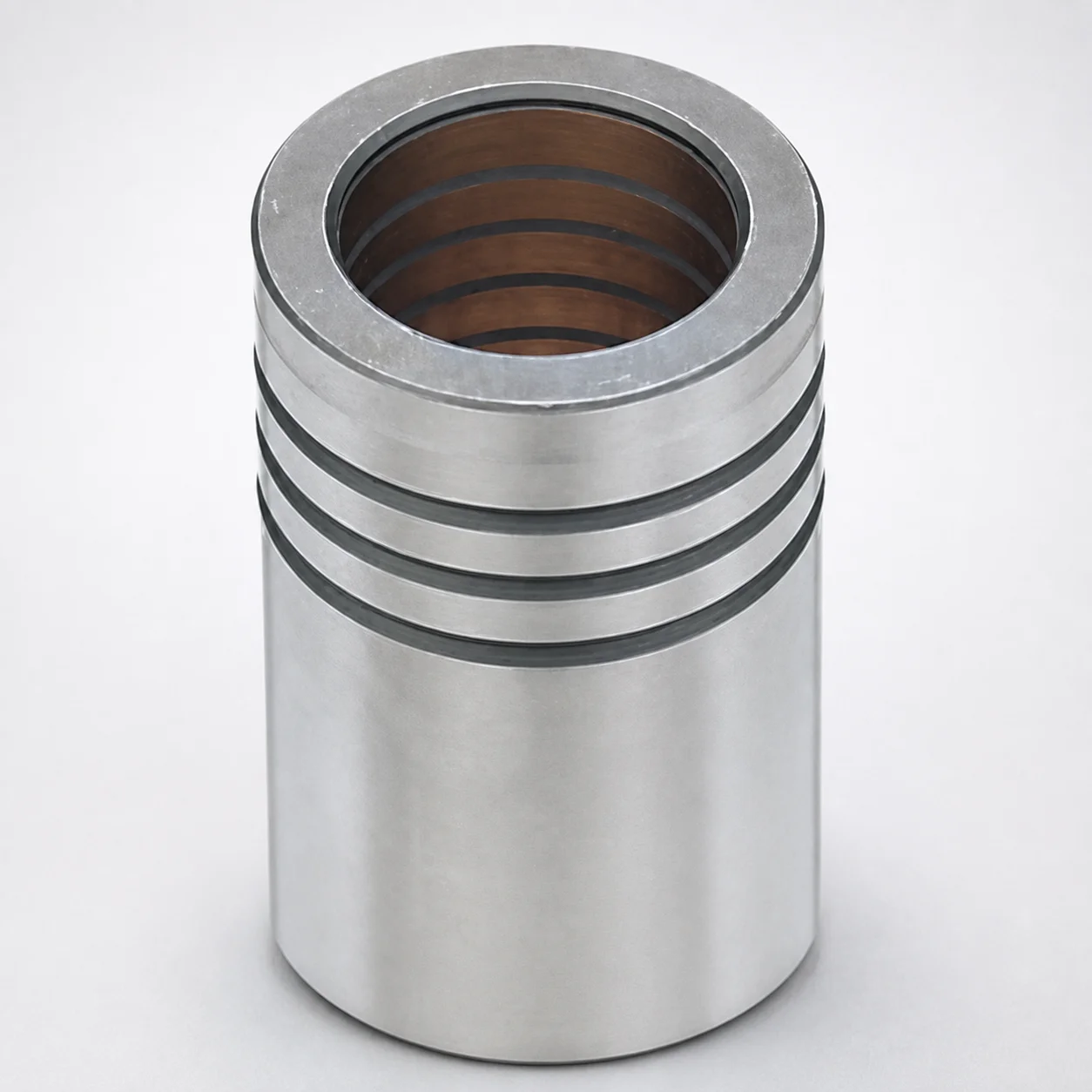
LFBZ Plain Guide Bushings for Die Sets (Oil-Free Copper Alloy) Loctite Bonded
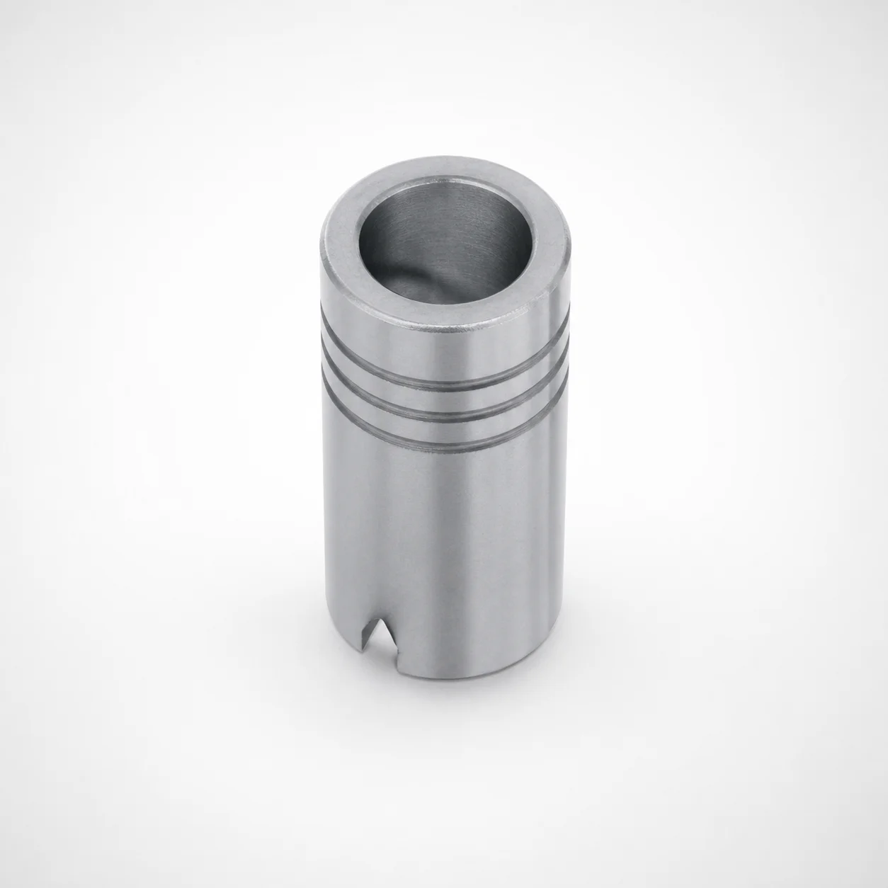
Plain Guide Bushings for Die Sets LDB
Need Custom Specifications?
Our engineering team can help with custom configurations, material selection, and volume pricing.