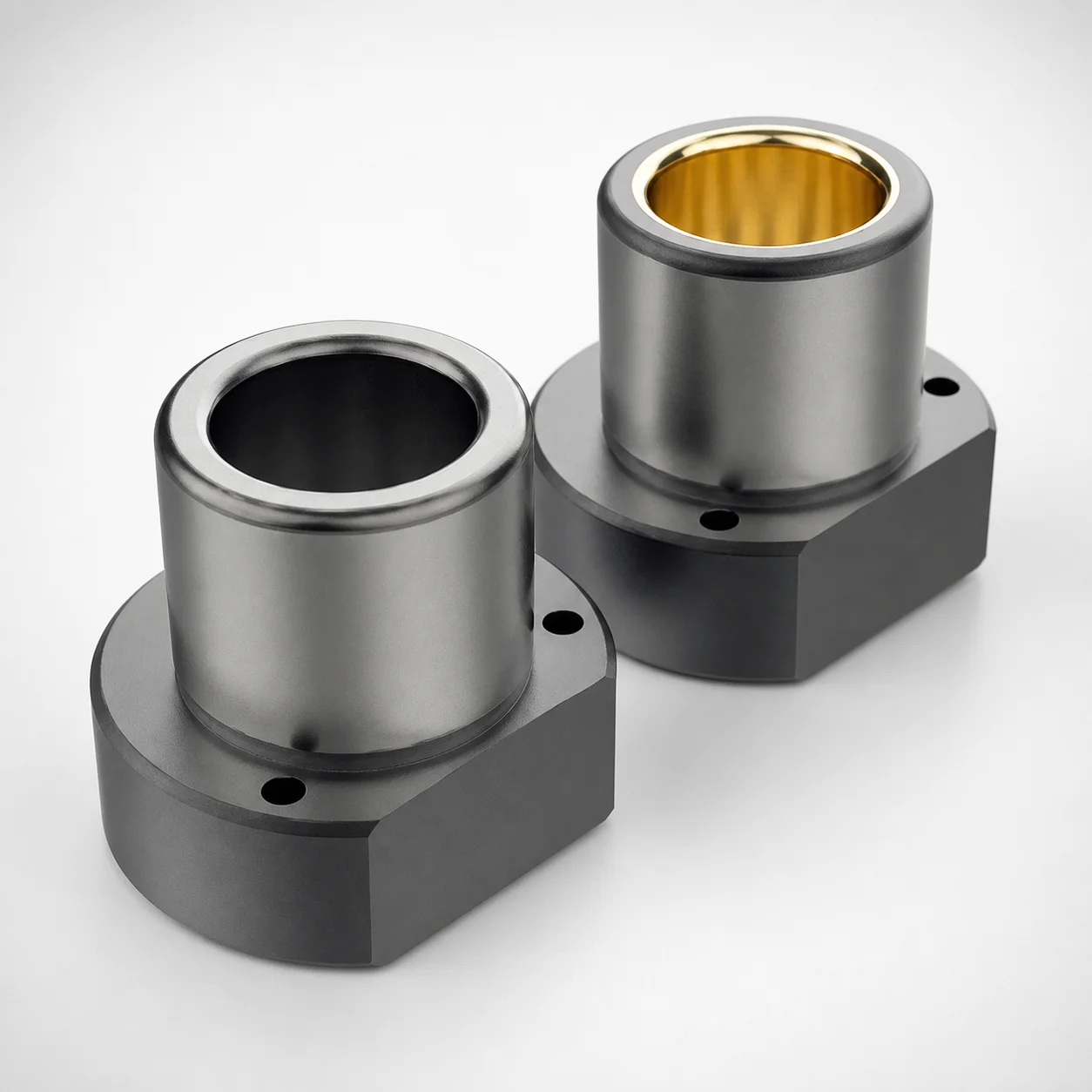
ISO 9448-4 Bronze Flanged Guide Bushings - One Side Flanged Long
Flanged guide bushings one side flanged long (ISO 9448-4) provide stable positioning for sliding die and mold components. Choose bronze bushing or coated bronze variants with hardness grades suited for wear-resistance in production.
- One side flanged long design helps maintain alignment under repeat motion
- Bronze bushing and coated bronze options support smooth guide performance
- Selectable hardness grades: 52~54 HRC or 61~63 HRC for durability
- Built to ISO 9448-4 for compatibility with standard guide bushing applications
Specifications
26 configurations available
| L (Length) (mm) | D (Diameter) (mm) | M (Material) | Hardness |
|---|---|---|---|
| 52 | 19 | 1.7131 / Bronze | 61~63 HRC |
| 52 | 19 | 1.7131 / Coating | 52~54 HRC |
| 52 | 20 | 1.7131 / Bronze | 61~63 HRC |
| 52 | 20 | 1.7131 / Coating | 52~54 HRC |
| 62 | 24 | 1.7131 / Bronze | 61~63 HRC |
| 62 | 24 | 1.7131 / Coating | 52~54 HRC |
| 62 | 25 | 1.7131 / Bronze | 61~63 HRC |
| 62 | 25 | 1.7131 / Coating | 52~54 HRC |
| 72 | 30 | 1.7131 / Bronze | 61~63 HRC |
| 72 | 30 | 1.7131 / Coating | 52~54 HRC |
| 72 | 32 | 1.7131 / Bronze | 61~63 HRC |
| 72 | 32 | 1.7131 / Coating | 52~54 HRC |
| 77 | 38 | 1.7131 / Bronze | 61~63 HRC |
| 77 | 38 | 1.7131 / Coating | 52~54 HRC |
| 77 | 40 | 1.7131 / Bronze | 61~63 HRC |
| 77 | 40 | 1.7131 / Coating | 52~54 HRC |
| 102 | 48 | 1.7131 / Bronze | 61~63 HRC |
| 102 | 48 | 1.7131 / Coating | 52~54 HRC |
| 102 | 50 | 1.7131 / Bronze | 61~63 HRC |
| 102 | 50 | 1.7131 / Coating | 52~54 HRC |
| 102 | 60 | 1.7131 / Bronze | 61~63 HRC |
| 102 | 60 | 1.7131 / Coating | 52~54 HRC |
| 102 | 63 | 1.7131 / Bronze | 61~63 HRC |
| 102 | 63 | 1.7131 / Coating | 52~54 HRC |
| 125 | 80 | 1.7131 / Bronze | 61~63 HRC |
| 125 | 80 | 1.7131 / Coating | 52~54 HRC |
Product Guide
Application Scenarios+
How it’s used: ISO 9448-4 flanged guide bushings are installed in leader/ejector guide sections to maintain parallel alignment between moving mold components during opening, ejecting, and return cycles.
Scenario 1—automotive connector & latch tooling: In sliding die and small moving inserts, the one-side flanged long geometry stabilizes lateral guidance, reducing wobble under repeated motion. Bronze (or coated bronze) is selected here because it promotes smooth sliding against the mating leader pin and helps control frictional wear.
Scenario 2—consumer electronics housings: For molds that cycle frequently with moderate loads, the controlled hardness options (52~54 HRC or 61~63 HRC) help tune wear resistance vs. galling tendency to match production speed and lubrication practices.
Scenario 3—general die alignment: When strict compatibility with standard guide bushing layouts is required, this variant follows ISO 9448-4 so engineers can reuse established clearances and assembly referencing across leader-bushing designs.
Material & Process Details+
Steel/bronze family: This guide bushing uses material grade 1.7131 as the bronze base. For the coated variant, 1.7131 / Coating applies an additional surface layer to improve sliding performance in guided motion.
Hardness (controlled wear performance): Available hardness levels are 61~63 HRC for higher wear resistance and 52~54 HRC for a more balanced toughness-to-wear trade-off under lower contact severity. Higher hardness generally reduces wear on the bushing surface, but can increase sensitivity to abrasive debris if lubrication is inconsistent.
- Bronze (1.7131): Designed for smooth guiding with good anti-friction behavior in many mold applications.
- Coated bronze (1.7131 / Coating): Chosen when reduced friction and improved scuff resistance are needed for faster cycles.
Heat treatment state: The provided data specifies hardness ranges rather than explicit quench/temper or nitriding steps; select the hardness grade to meet the wear and contact conditions of your leader system.
Sizing & Selection Guide+
Key dimensions: This product is defined by L (length) and D (diameter). Select D within 19 ~ 80 mm to match the leader pin/guide interface, and choose L from 52, 62, 72, 77, 102, 125 mm to achieve the required bearing length.
Matching mold requirements: Use the bushing length (L) to control how much of the leader pin is supported. Longer L improves stability for long-stroke sliding components, which is especially relevant for the one-side flanged long configuration that helps maintain alignment under repeated motion.
- Fit considerations: Use your drawing’s intended clearance between leader and bushing and verify compatibility with your ISO 9448-4-based layout.
- Tolerance checks: Because no tolerance values are provided in the data, confirm your internal acceptance criteria against the mating leader pin tolerance and surface finish.
- Configuration: Diameter and length are fixed options (from the ranges above), while material and hardness are selectable (bronze vs. coated bronze; 52~54 HRC or 61~63 HRC).
Frequently Asked Questions
Which hardness grade should I choose for a long-stroke leader bushing: 52~54 HRC or 61~63 HRC?+
When is the coated bronze (1.7131 / Coating) variant preferable to plain bronze (1.7131)?+
How do I select the correct diameter D for this ISO 9448-4 guide bushing?+
How should I choose the bushing length L for one-side flanged long guidance?+
Is this bushing compatible with standard ISO 9448-4 leader guide designs?+
Related Products
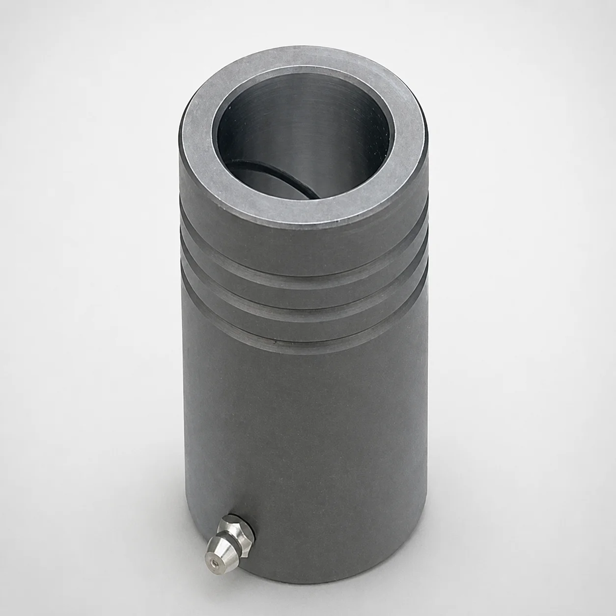
MDB Type Plain Guide Bushings for Die Sets (Oil Groove) Bonded by Devcon Adhesive
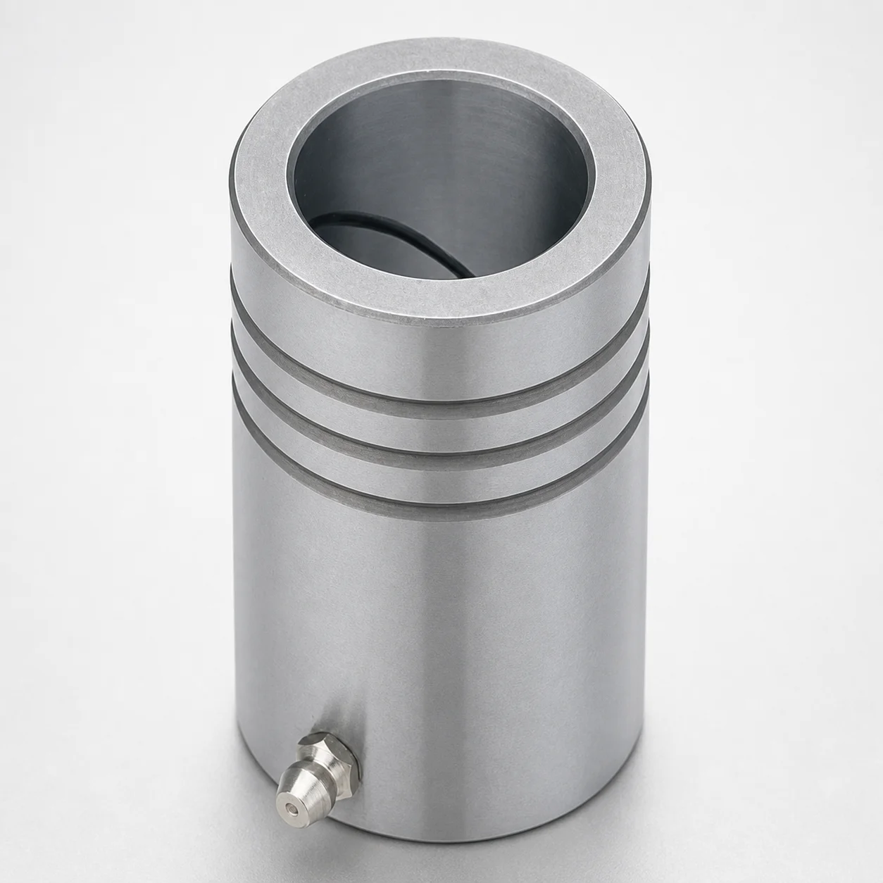
LDB Plain Guide Bushings for Die Sets
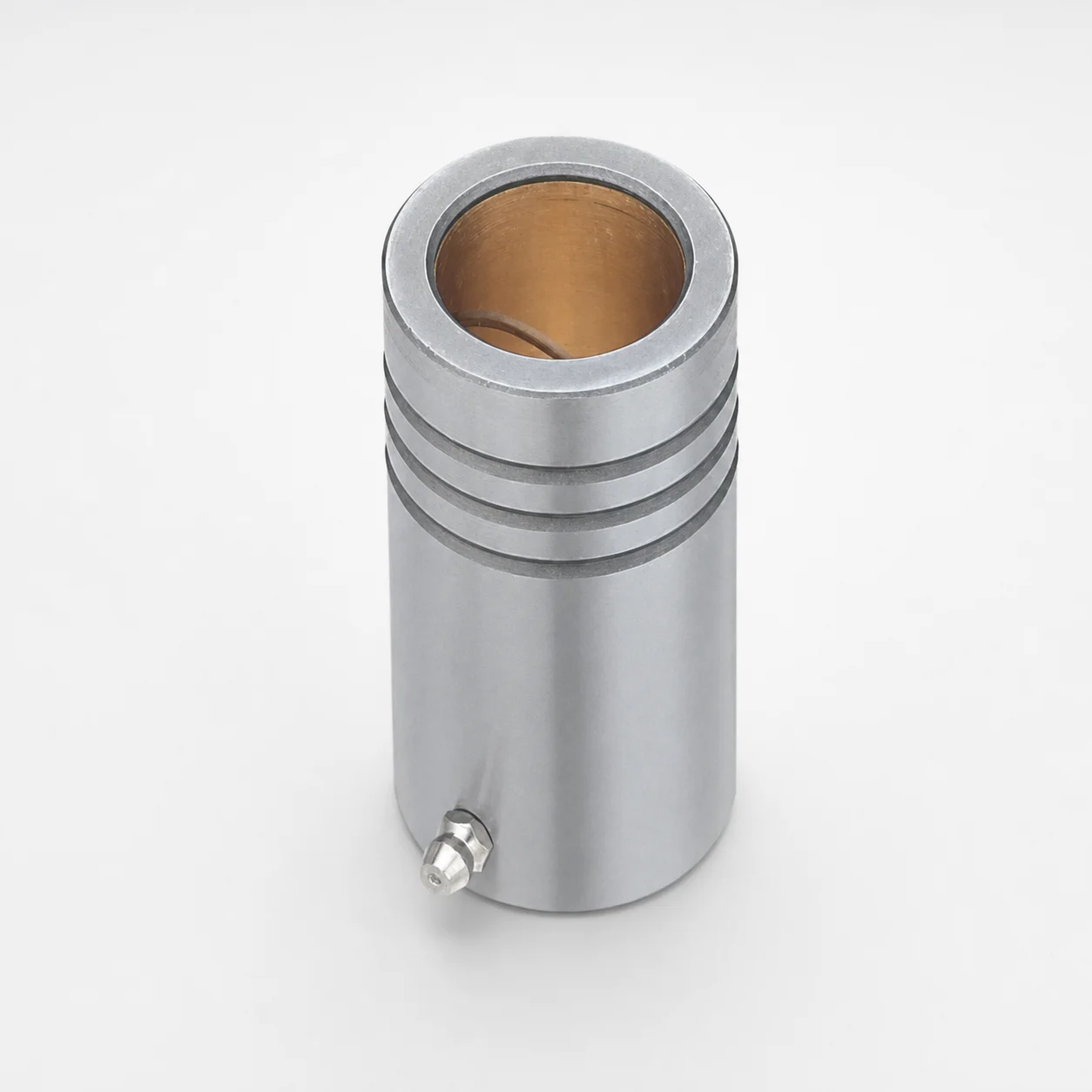
LFB Plain Guide Bushings for Die Sets with Oil Groove, Loctite Adhesive
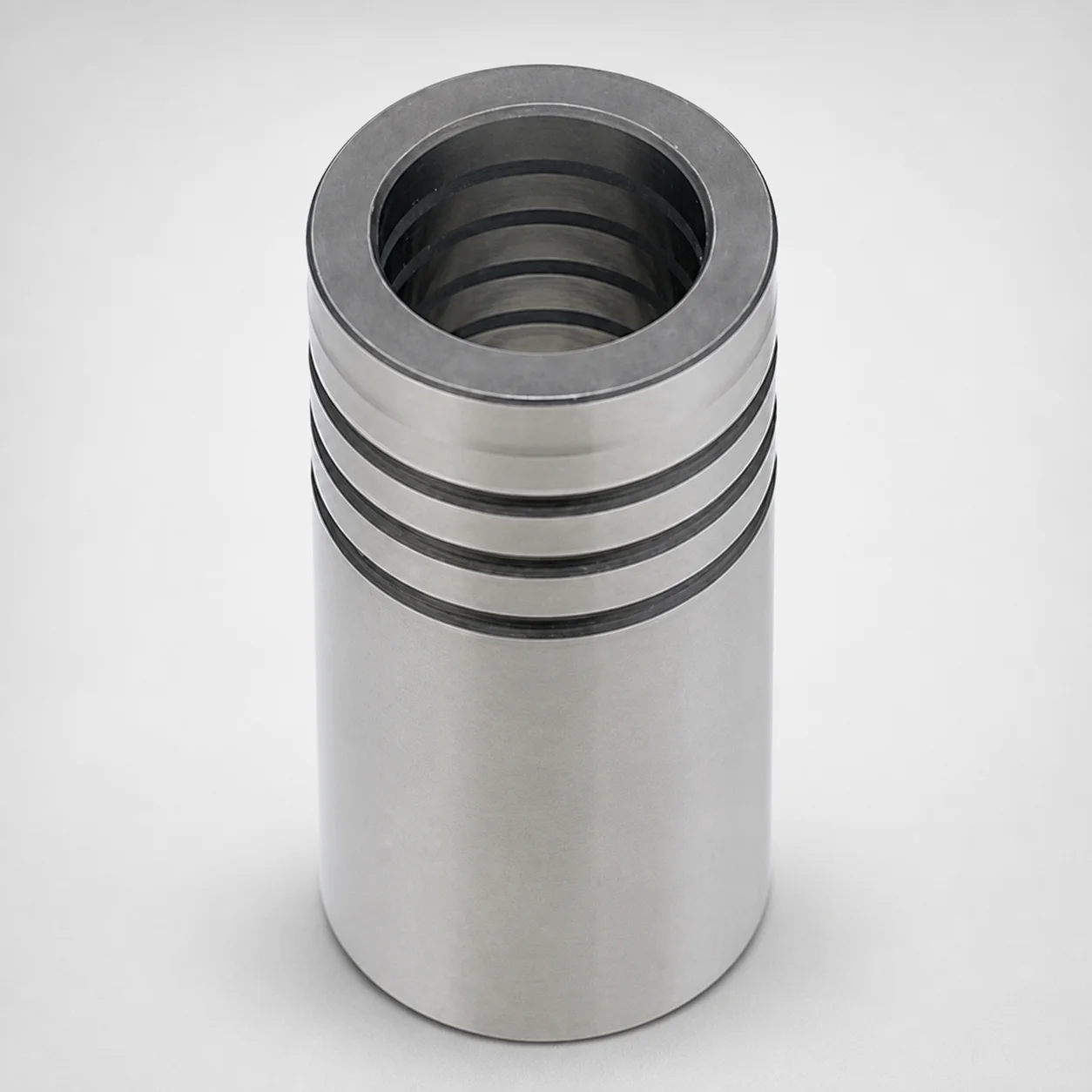
DIN Standard Oil-Free Plain Guide Bushings LDBZ
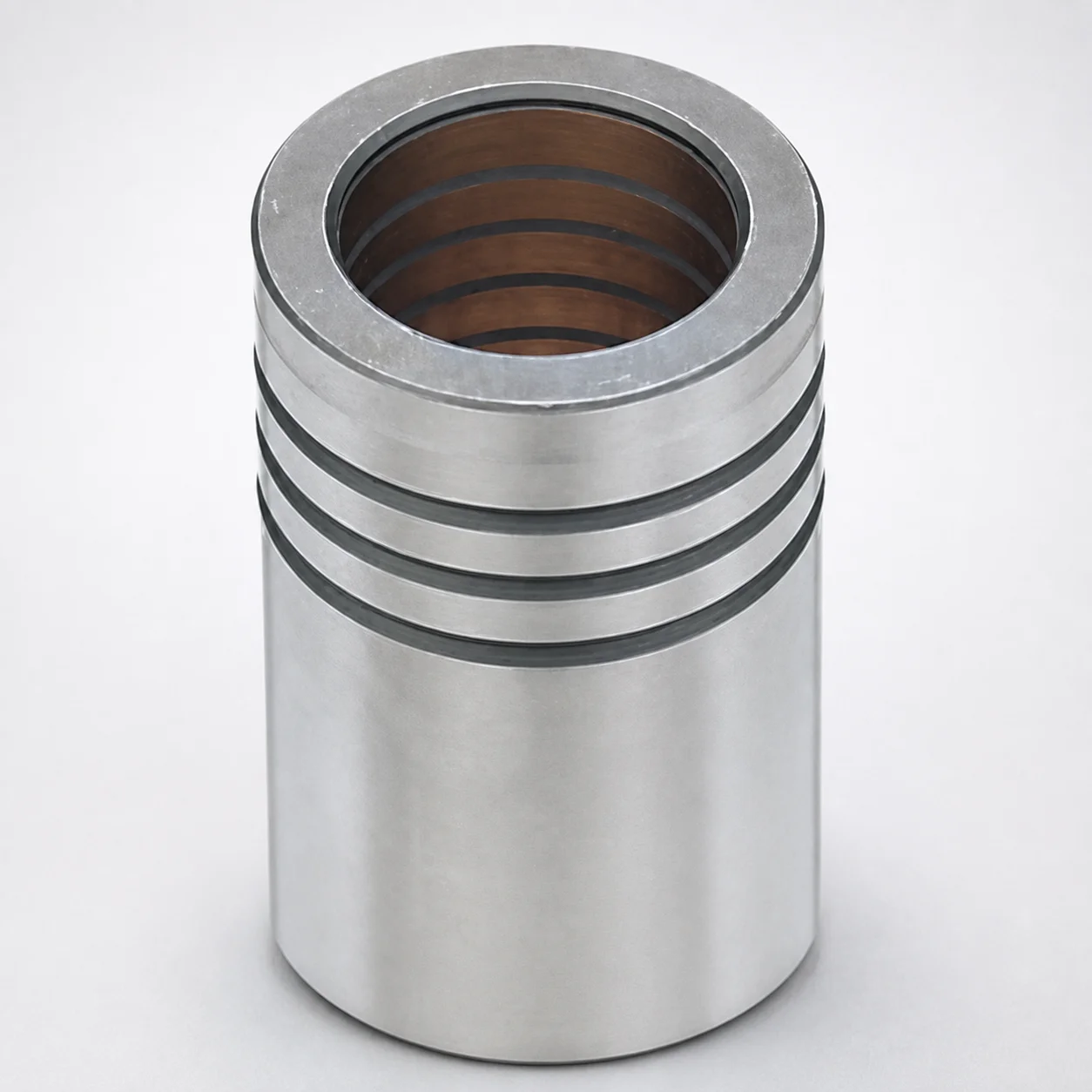
LFBZ Plain Guide Bushings for Die Sets (Oil-Free Copper Alloy) Loctite Bonded
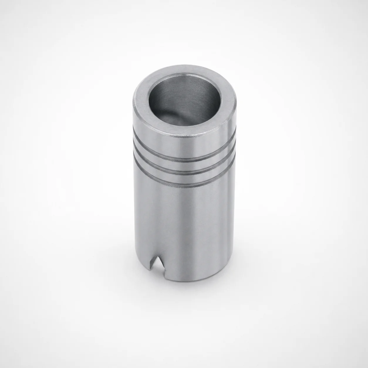
Plain Guide Bushings for Die Sets LDB
Need Custom Specifications?
Our engineering team can help with custom configurations, material selection, and volume pricing.