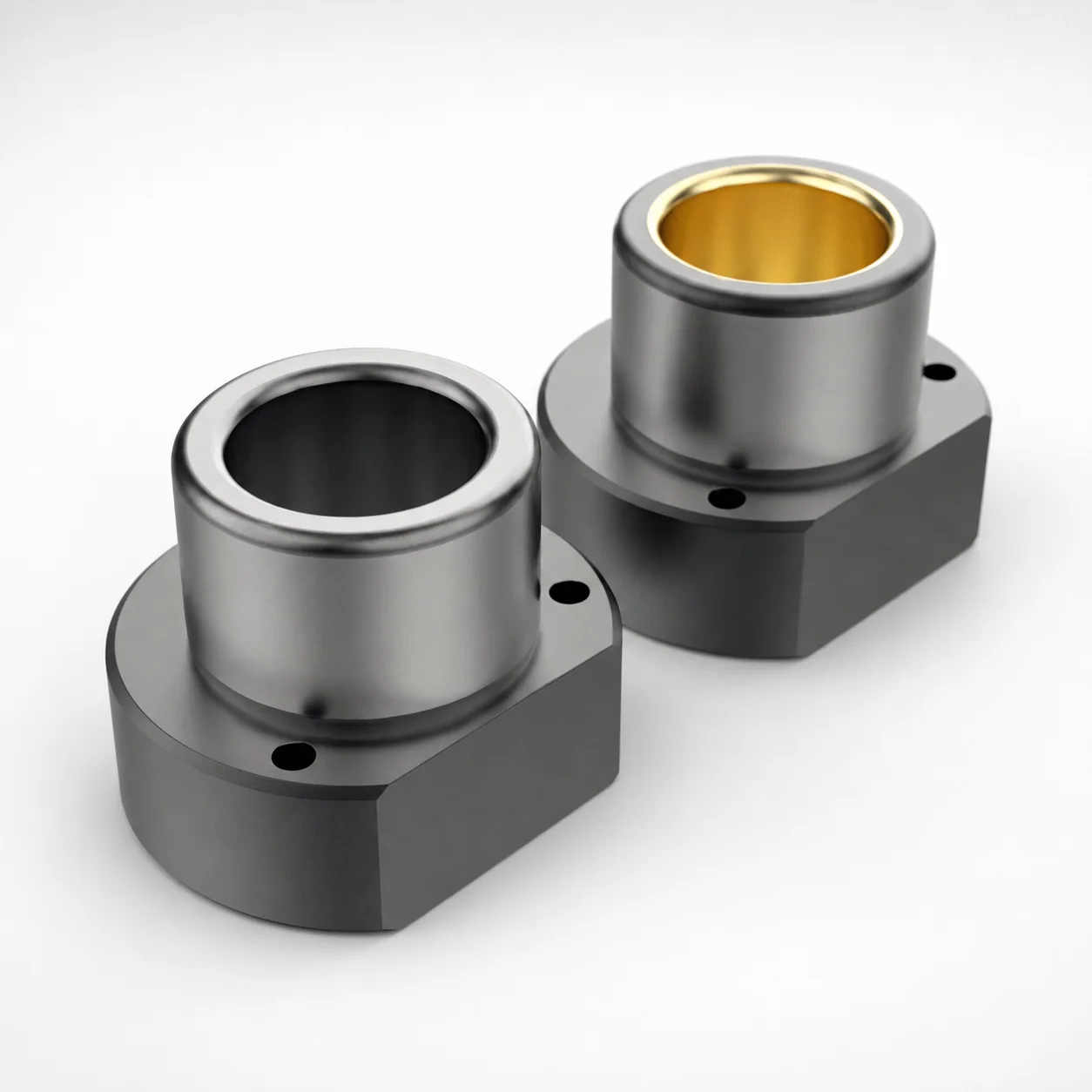
ISO 9448-4 Bronze Flanged Guide Bushings - One Side Flanged
Flanged guide bushings - one side flanged (bronze) are designed to stabilize die guidance and improve alignment in repetitive press operations. The flanged medium-height profile helps locate the bushing reliably during assembly.
- One-side flanged, medium-height construction for consistent die alignment
- Bronze bushing with 61~63 HRC or coated option at 52~54 HRC
- Engineered for guide fit applications under controlled wear and friction
- Built to ISO 9448-4 for standardized interchangeability
Specifications
24 configurations available
| L (Length) (mm) | D (Diameter) (mm) | M (Material) | Hardness |
|---|---|---|---|
| 45 | 19 | 1.7131 / Bronze | 61~63 HRC |
| 45 | 19 | 1.7131 / Coating | 52~54 HRC |
| 45 | 20 | 1.7131 / Bronze | 61~63 HRC |
| 45 | 20 | 1.7131 / Coating | 52~54 HRC |
| 55 | 24 | 1.7131 / Bronze | 61~63 HRC |
| 55 | 24 | 1.7131 / Coating | 52~54 HRC |
| 55 | 25 | 1.7131 / Bronze | 61~63 HRC |
| 55 | 25 | 1.7131 / Coating | 52~54 HRC |
| 62 | 30 | 1.7131 / Bronze | 61~63 HRC |
| 62 | 30 | 1.7131 / Coating | 52~54 HRC |
| 62 | 32 | 1.7131 / Bronze | 61~63 HRC |
| 62 | 32 | 1.7131 / Coating | 52~54 HRC |
| 67 | 38 | 1.7131 / Bronze | 61~63 HRC |
| 67 | 38 | 1.7131 / Coating | 52~54 HRC |
| 67 | 40 | 1.7131 / Bronze | 61~63 HRC |
| 67 | 40 | 1.7131 / Coating | 52~54 HRC |
| 89 | 48 | 1.7131 / Bronze | 61~63 HRC |
| 89 | 48 | 1.7131 / Coating | 52~54 HRC |
| 89 | 50 | 1.7131 / Bronze | 61~63 HRC |
| 89 | 50 | 1.7131 / Coating | 52~54 HRC |
| 89 | 60 | 1.7131 / Bronze | 61~63 HRC |
| 89 | 60 | 1.7131 / Coating | 52~54 HRC |
| 89 | 63 | 1.7131 / Bronze | 61~63 HRC |
| 89 | 63 | 1.7131 / Coating | 52~54 HRC |
Product Guide
Application Scenarios+
Where it’s used: These ISO 9448-4 bronze flanged guide bushings fit into leader/ejector tooling to keep moving parts aligned during repetitive injection and press operations, especially when long stroke guidance is critical.
- Automotive connector and sensor housings: Use the one-side flanged profile to stabilize die-to-plate alignment and reduce guide shift over many cycles. The medium-height flange improves locating repeatability during bushing installation.
- Appliance and consumer device enclosures: In molds with frequent parting line opening and ejector travel, the bronze guide surface helps maintain smooth friction behavior and controlled wear in guide fit systems.
- General repetitive press forming inserts: The hardened bronze variants (61~63 HRC) are suited for longer life under dry sliding and alignment-critical motion.
Why this variant: Built to ISO 9448-4, the bushings support standardized interchangeability across compatible leader-bushing assemblies, helping engineers maintain consistent guide clearance and alignment performance.
Material & Process Details+
Material system: The bushing body uses 1.7131 Bronze (also listed as a coated option). Bronze provides stable bearing behavior under sliding contact and is commonly selected for guide fit applications where friction and wear must be controlled.
- Hardened option: 61~63 HRC for higher wear resistance and longer guidance life in repetitive operation.
- Coated / lower hardness option: 52~54 HRC to balance toughness and reduce sensitivity to impact or installation variation, while the coating supports friction/wear management.
Hardness trade-off: The higher-hardness variant improves wear resistance, while the 52~54 HRC coated option can be preferred when toughness and resistance to localized loading are more critical.
Heat-treatment state: Available as hardened bronze at the specified HRC levels (and a coated option with the lower hardness range), enabling engineers to choose the right durability vs. robustness profile for their guide clearance strategy.
Sizing & Selection Guide+
Step 1—Match the guide diameter (D): Select the bushing diameter from 19 ~ 63 mm so it matches the leader/guide fit design. Ensure the chosen diameter aligns with your intended clearance so the bushing can guide without binding.
Step 2—Match the working length (L): Choose L = 45, 55, 62, 67, or 89 mm based on the effective guidance length in your mold assembly (core/cavity alignment requirements plus overlap for stable centering).
Step 3—Use the flange for install location: Because this is a one-side flanged bushing, confirm the flange side placement corresponds to your die/plate locating surfaces. The flange helps repeat alignment during assembly, improving consistency across rebuilds.
- Tolerance/fit note: Use your standard mold guide-fit tolerance practice for bronze bushings; hardness changes (61~63 HRC vs. 52~54 HRC) can affect wear rate and running behavior, so validate clearances against your cycle conditions.
- Configurable dimensions: L and D are selectable within the listed ranges; M/material variant (bronze vs. coated) is a separate selection.
Frequently Asked Questions
Which hardness should I choose for long-life guide fit in repetitive injection cycles: 61~63 HRC bronze or the 52~54 HRC coated option?+
How do I select the correct bushing length L for stable die alignment?+
What diameter range is supported, and how does diameter D affect guide fit clearance?+
Does ISO 9448-4 compliance improve interchangeability across mold builds?+
Is this bushing suitable as a one-side flanged locating component—how should I orient it during assembly?+
Related Products
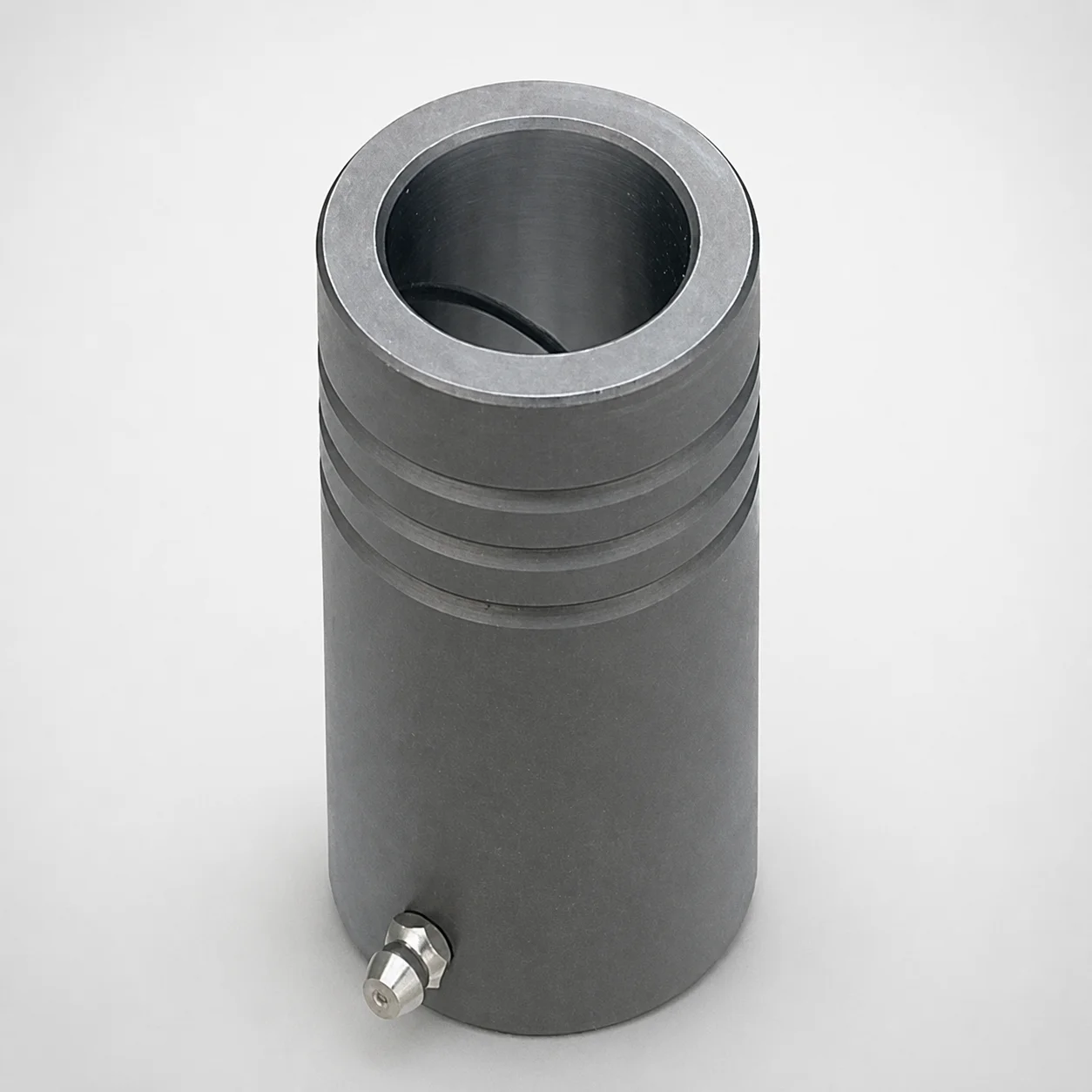
MDB Type Plain Guide Bushings for Die Sets (Oil Groove) Bonded by Devcon Adhesive
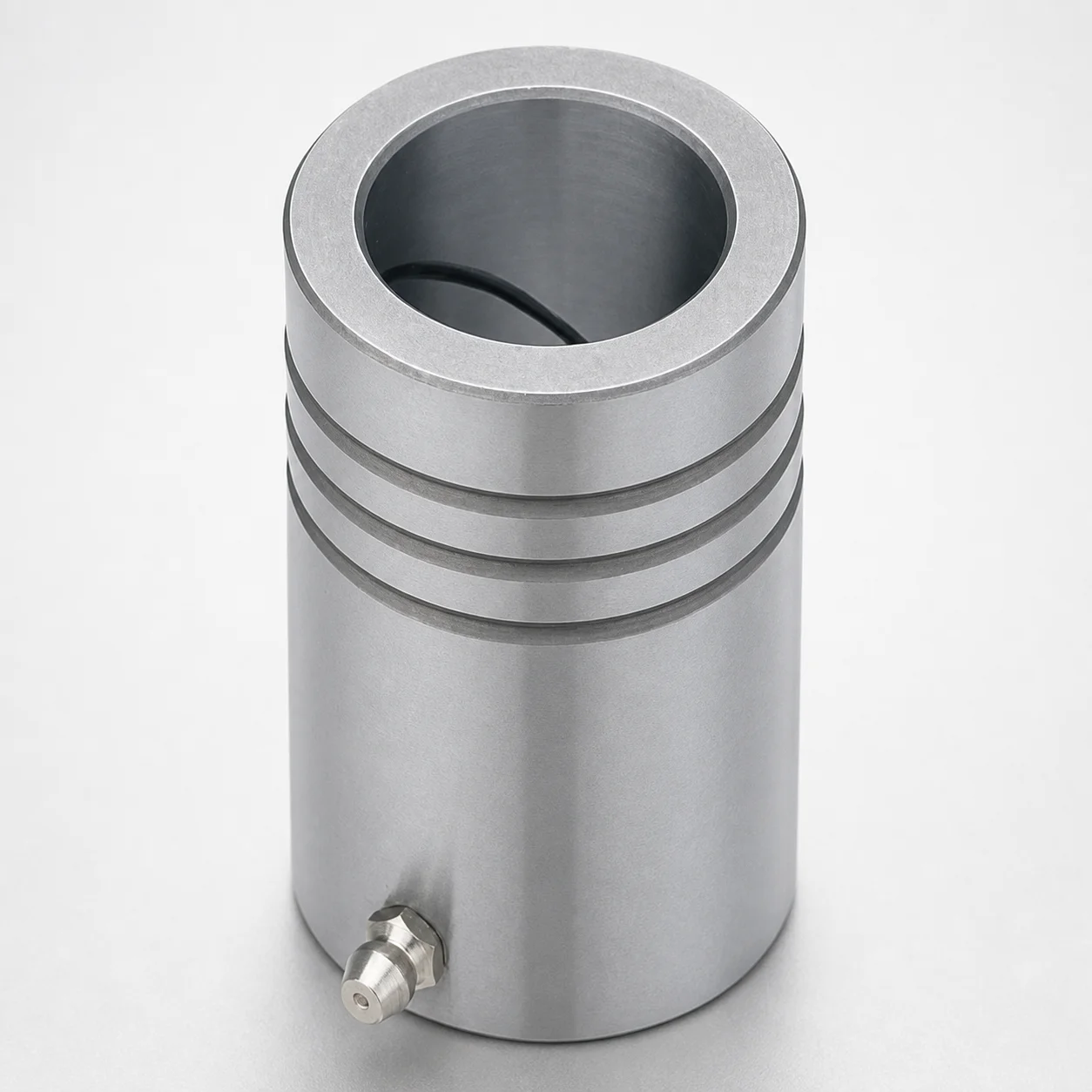
LDB Plain Guide Bushings for Die Sets
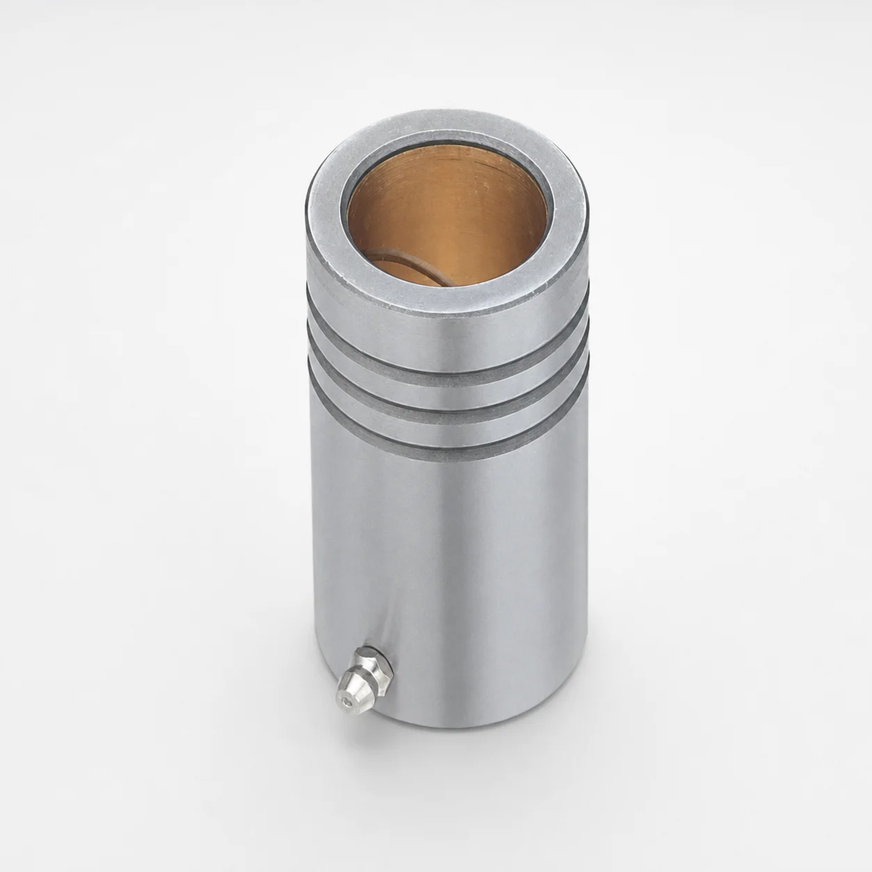
LFB Plain Guide Bushings for Die Sets with Oil Groove, Loctite Adhesive
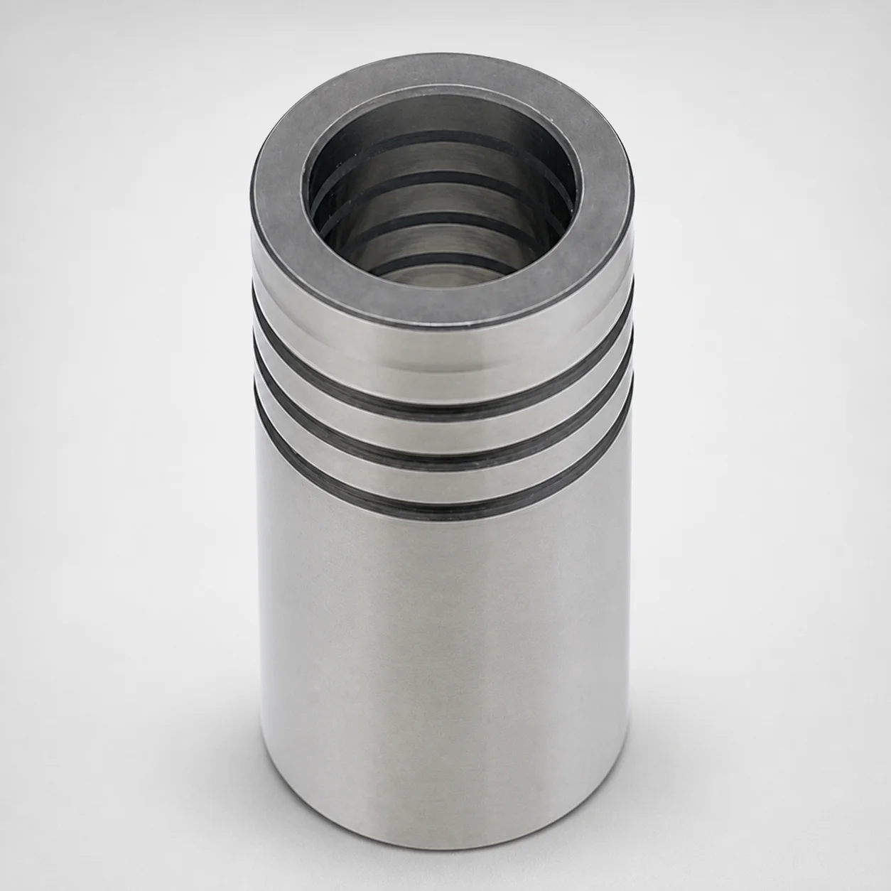
DIN Standard Oil-Free Plain Guide Bushings LDBZ
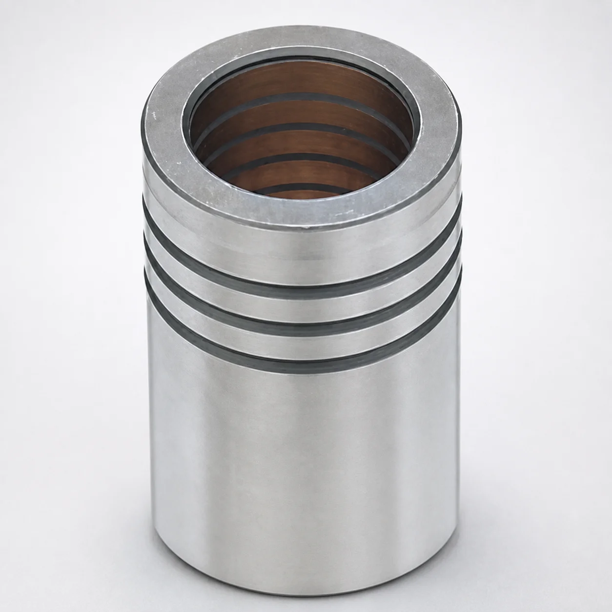
LFBZ Plain Guide Bushings for Die Sets (Oil-Free Copper Alloy) Loctite Bonded
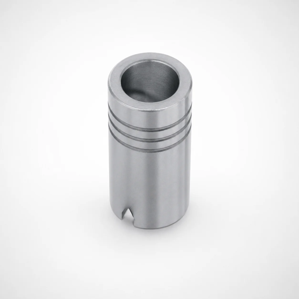
Plain Guide Bushings for Die Sets LDB
Need Custom Specifications?
Our engineering team can help with custom configurations, material selection, and volume pricing.