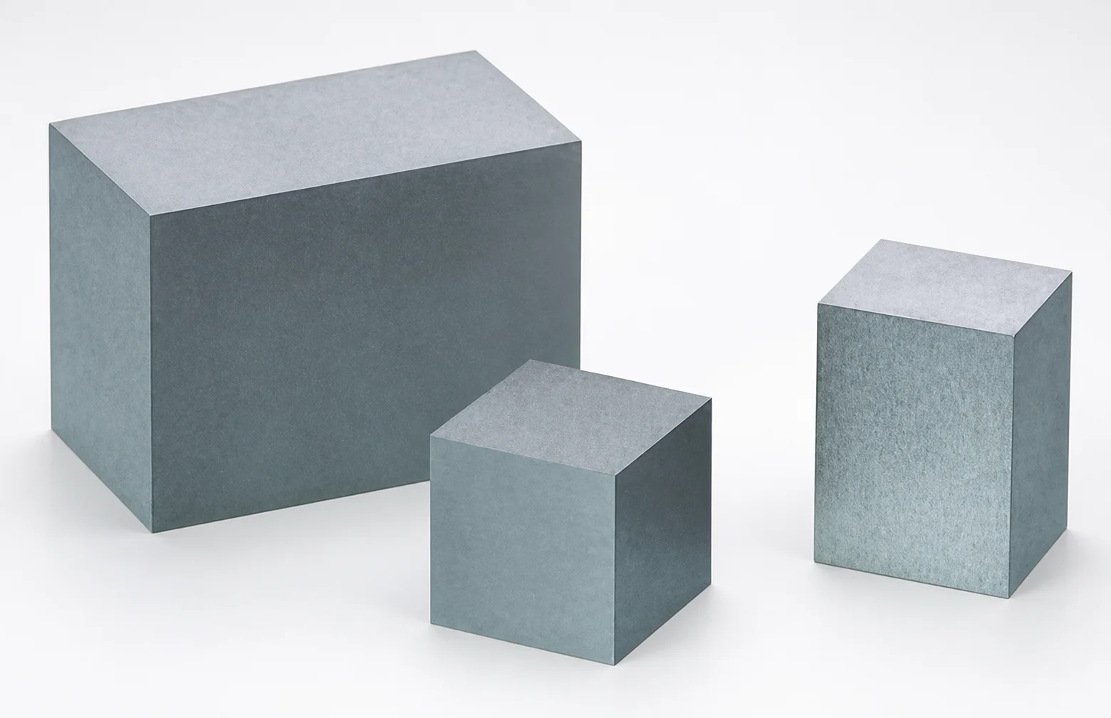
Various Steels Cavity Insert Block Blanks Reference Plane
Various steels cavity insert block blanks offer precision components for die and cavity build-up, with dimensional control to support consistent part production. Reference plane options help streamline locating and downstream machining.
- Reference plane option improves alignment for repeatable cavity assembly
- Choose from NAK55/NAK80/DH2F and tool steels for fit-to-application selection
- Engineered dimensional accuracy supports reliable downstream machining and stack-up
- Available polished face/grind options support smooth finishing workflows
Specifications
17 configurations available
| Polished Surface | Material | Reference Plane | A (Width) (mm) | B (Length) (mm) | T (Thickness) (mm) | type |
|---|---|---|---|---|---|---|
| 6 face-milled | DH2F | No | 8 ~ 200 | 8 ~ 300 | 8 ~ 60 | - |
| 6 face-milled | HPM38 | No | 8 ~ 200 | 8 ~ 300 | 8 ~ 60 | - |
| 6 face-milled | NAK55 | No | 8 ~ 200 | 8 ~ 300 | 8 ~ 100 | - |
| 6 face-milled | NAK80 | No | 10 ~ 200 | 8 ~ 300 | 8 ~ 100 | - |
| 6 face-milled | PX5 | No | 8 ~ 200 | 8 ~ 300 | 8 ~ 100 | - |
| 6 face-milled | RIGOR | No | 8 ~ 200 | 8 ~ 300 | 8 ~ 60 | - |
| 4 face-grinded/2 face-milled | RIGOR | Yes | 8 ~ 200 | 8 ~ 300 | 15 ~ 60 | - |
| 4 face-grinded/2 face-milled | RIGOR | Yes | 8 ~ 200 | - | 15 ~ 60 | - |
| 6 face-milled | S50C annealed | No | 8 ~ 200 | 8 ~ 300 | 8 ~ 100 | - |
| 4 face-grinded/2 face-milled | S50C annealed | Yes | 8 ~ 200 | 8 ~ 300 | 8 ~ 60 | - |
| 6 face-milled | S50C Refined steel | No | 8 ~ 200 | 8 ~ 300 | 8 ~ 60 | - |
| 6 face-milled | S-STAR | No | 8 ~ 200 | 8 ~ 300 | 8 ~ 60 | - |
| 6 face-milled | SKD11 | No | 8 ~ 200 | 8 ~ 300 | 8 ~ 60 | - |
| 4 face-grinded/2 face-milled | SKD11 | Yes | 8 ~ 200 | 8 ~ 300 | 8 ~ 60 | - |
| 6 face-milled | SKD61 | No | 8 ~ 200 | 8 ~ 300 | 8 ~ 60 | - |
| 4 face-grinded/2 face-milled | SKD61 | Yes | 8 ~ 200 | 8 ~ 300 | 8 ~ 60 | - |
| 6 face-milled | STAVAX ESR annealed | No | 8 ~ 200 | 8 ~ 300 | 8 ~ 60 | - |
Product Guide
Application Scenarios+
Large die-casting and mold build-up: These cavity insert block blanks with an optional reference plane are used as precision bases for building cavity surfaces in multi-part die sets. The reference plane (when selected) supports consistent alignment during cavity assembly, helping reduce stack-up variation before machining.
Automotive and industrial components: When cavities require stable dimensional control across repeated cycles, the option to choose from tool steels and pre/post-treated steels (including DH2F, NAK55, and SKD61) helps match hardness and wear needs to the expected shot count.
High-finish mold inserts: Polished face options—configured as 6 face-milled or 4 face-grinded / 2 face-milled—reduce finishing time for housings, visible surfaces, and functional cavity regions where consistent texture transfer matters.
- Reference plane option improves location repeatability for downstream cavity machining.
- Steel selection tailors hardness/wear trade-offs for die and mold environments.
Material & Process Details+
This series is offered in multiple steels so engineers can align hardness, wear resistance, and toughness to the casting or molding process. Common selections include DH2F, NAK55, NAK80, and SKD11/SKD61 type tool steels, plus lower-cost S50C variants for applications where machining and cost dominate.
- SKD61 (H13 equivalent class): typically chosen for a balanced combination of heat-check resistance and toughness for die-casting/mold service.
- SKD11: generally selected where higher wear resistance and dimensional stability are priorities for tooling.
- NAK55/NAK80: often used when fine surface quality and good wear behavior are needed for cavity surfaces.
- STAVAX ESR annealed, S50C annealed/refined: provided for predictable machinability; performance then depends on your subsequent hardening workflow.
Polished workflows (face-milled vs. face-grinded) are compatible with both hardened and machined-from-blank build-ups, but the final hardness depends on the selected material state (e.g., annealed vs. tool-steel grade suitable for hardening).
Sizing & Selection Guide+
Select the insert blank dimensions to match the cavity/core pocket envelope and machining allowance for your final cavity shape. The series provides A (Width) as variable in two ranges: 8–200 mm and 10–200 mm. The B (Length) is fixed to 8–300 mm, while T (Thickness) is variable across 8–60 mm, 8–100 mm, or 15–60 mm depending on the configuration.
- Match the cavity/core locating face: choose Reference Plane = Yes when you need a dedicated datum for consistent assembly positioning; choose No when you will create your own datum surfaces during machining.
- Plan allowances: keep sufficient stock for face polishing, grinding, or final cavity machining based on whether your face is face-milled or face-grinded.
- Fit considerations: if the insert interfaces with surrounding blocks, verify shoulder/step clearances and ensure the reference plane (when used) aligns with your cavity assembly datum to minimize variation.
Frequently Asked Questions
How do the optional reference plane configurations affect cavity insert block alignment in large die builds?+
When Reference Plane = Yes, the blank provides a dedicated locating face to improve repeatable alignment during cavity assembly. This reduces stack-up variation before downstream machining and helps maintain dimensional accuracy across build-up stages. If you choose Reference Plane = No, you can machine your own datums but must control alignment manually during assembly.
Which material options in this series are typically chosen for die-casting versus higher-surface-finish cavity work?+
This series lists multiple steel grades such as SKD11, SKD61, DH2F, and NAK55/NAK80, plus STAVAX ESR and S50C annealed/refined steels. For die-casting/mold service where heat checking and toughness are important, grades like SKD61 (H13-equivalent class) are commonly selected. For cavity surfaces that benefit from fine surface behavior, NAK55/NAK80 are often chosen, with finishing supported by the provided polished face options.
What are the available dimension ranges for A, B, and T, and how should I select thickness for cavity machining allowances?+
Width A is available in 8–200 mm or 10–200 mm. Length B is fixed to the range 8–300 mm, while thickness T is available as 8–60 mm, 8–100 mm, or 15–60 mm depending on configuration.
To select thickness, ensure you leave adequate stock for your planned face preparation and cavity finishing. If you require grinding for a tighter surface requirement, starting with more robust thickness (e.g., up to T = 100 mm where offered) can help maintain structural support during machining.
What is the difference between the polished surface options (6 face-milled vs. face-grinded combinations) for downstream machining?+
The polished surface variable is specified as either 6 face-milled or 4 face-grinded / 2 face-milled. The mixed grind/mill configuration can reduce the time needed for achieving a controlled finish on the ground faces. Your final cavity finish still depends on the selected steel grade and your finishing process, but choosing a grinded face option can improve workflow consistency.
Related Products
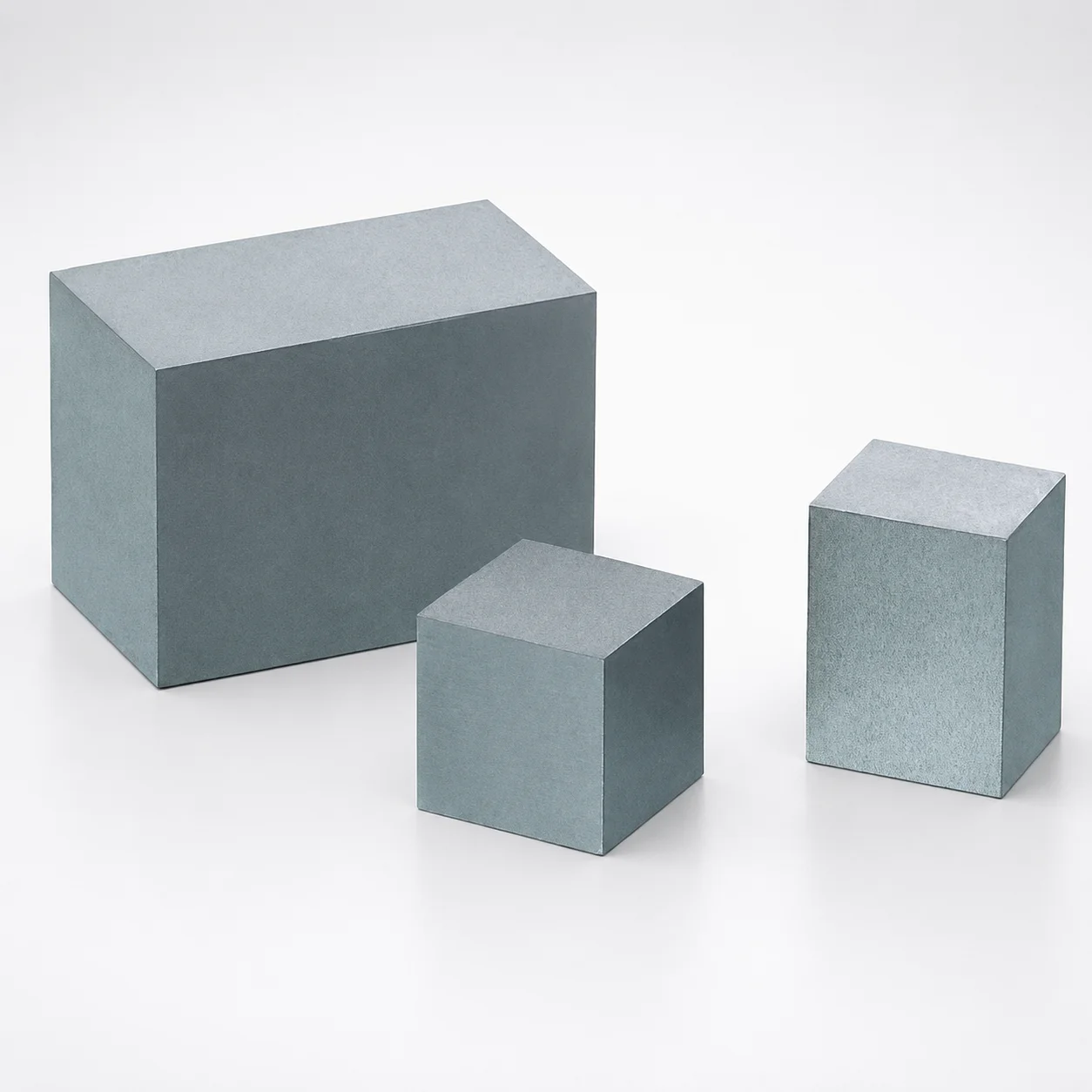
Various Steels 6-Face Ground Cavity Insert Blocks
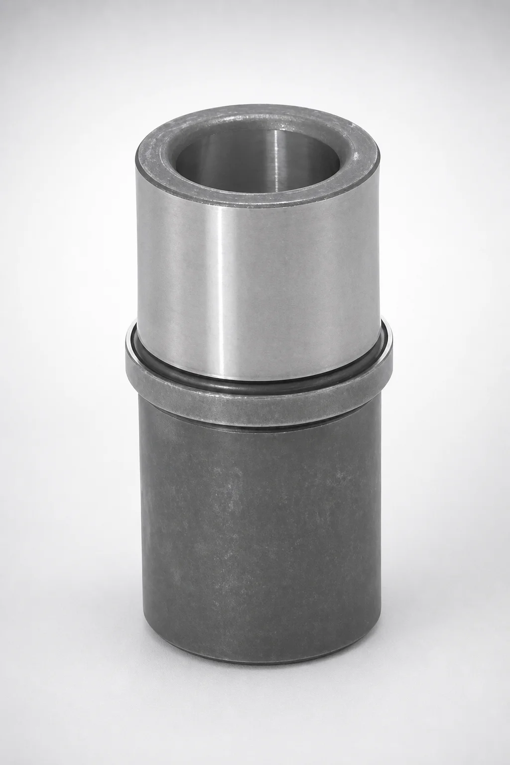
EGBN Type Ejector Leader Bushings Long Guide, Oil Grooves, SUJ2 Bearing Steel
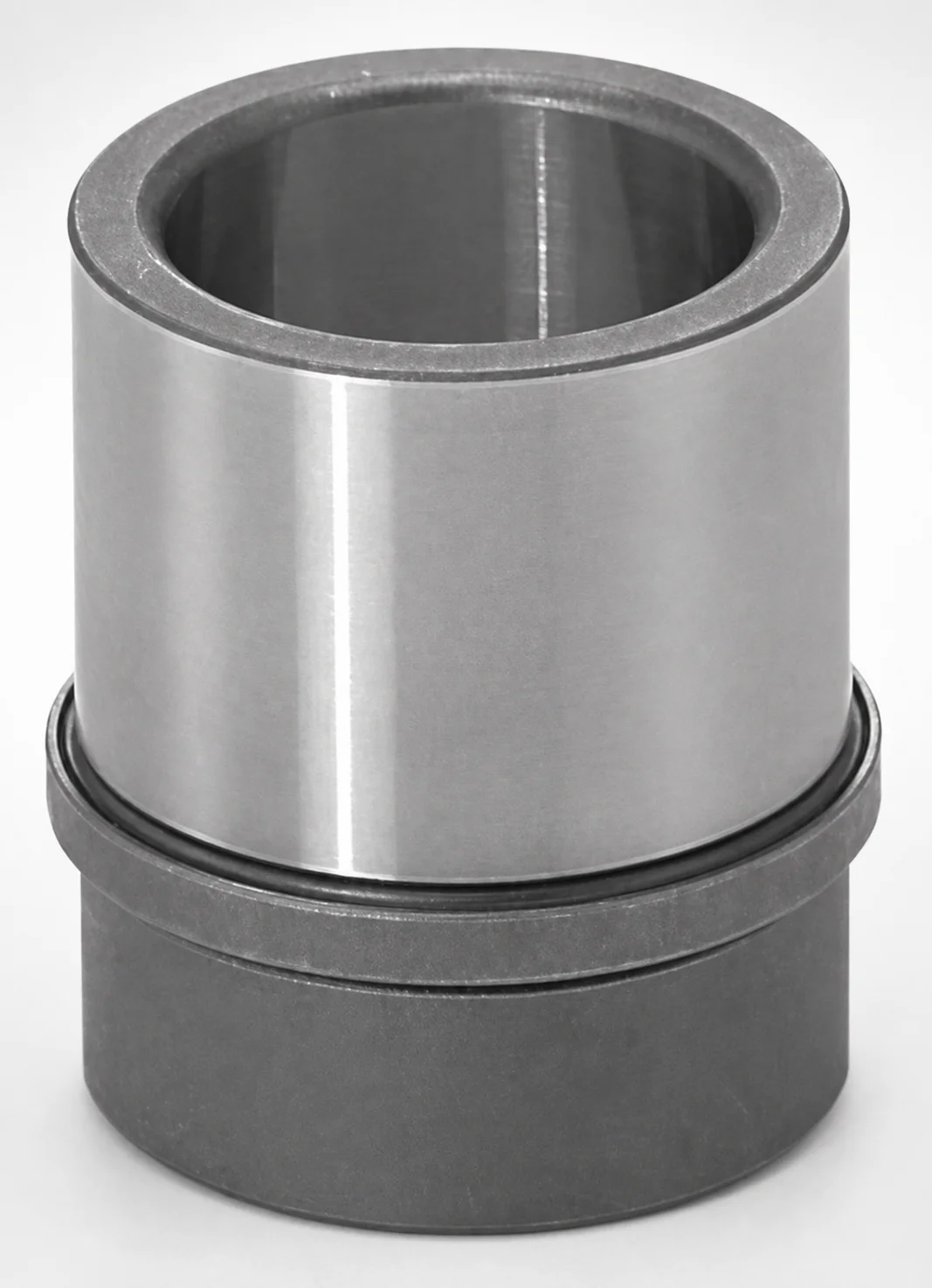
Ejector Leader Bushings - Oil Grooves SUJ2 Bearing Steel
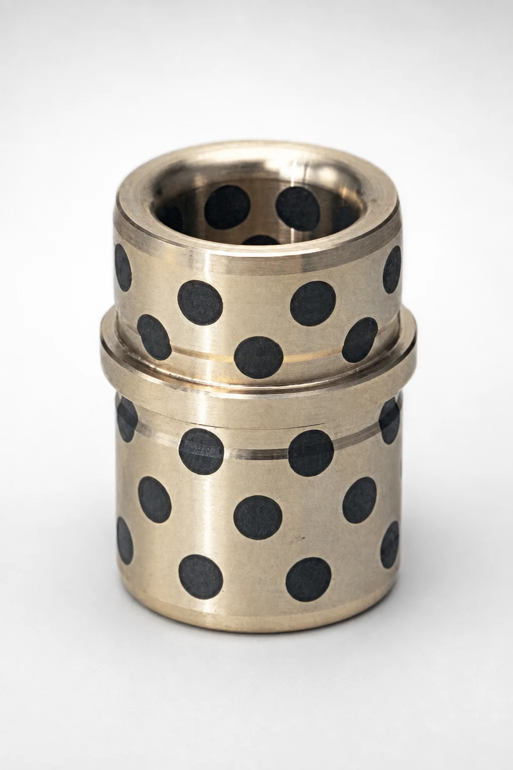
EGBZ Oil-Free Ejector Leader Bushings Long Guide
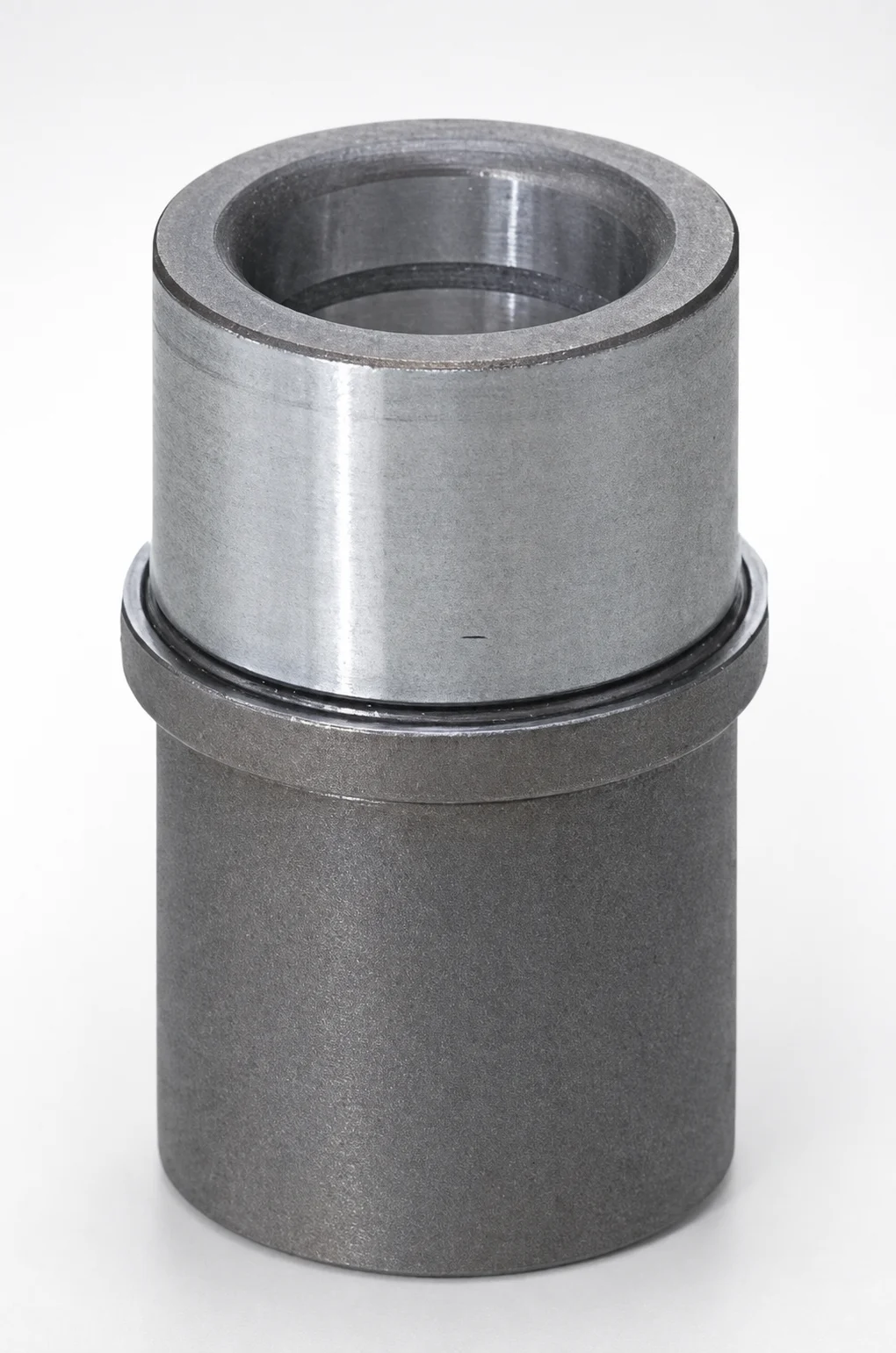
EGBNZ Type Oil-Free Ejector Leader Bushings Long Guide SUJ2 Bearing Steel
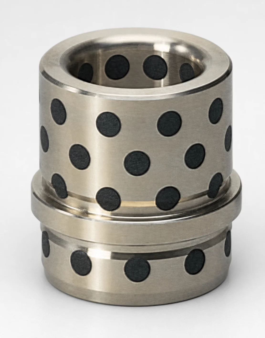
EGBZS Type Oil-Free Ejector Leader Bushings - Copper Alloy
Need Custom Specifications?
Our engineering team can help with custom configurations, material selection, and volume pricing.