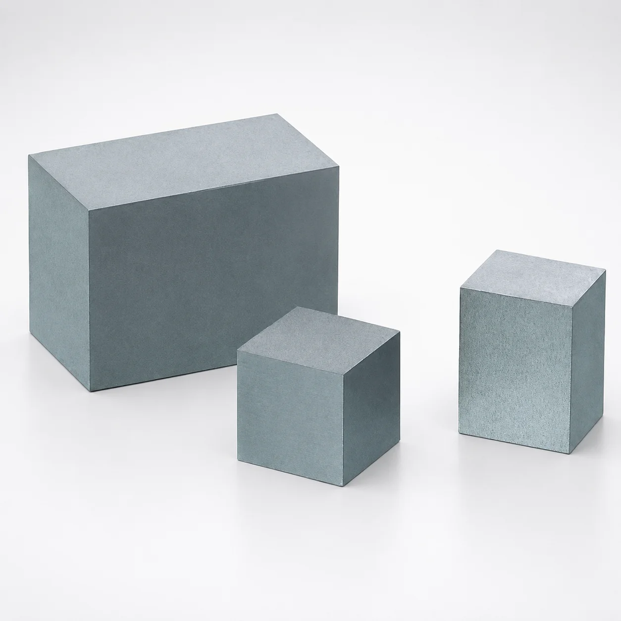
Various Steels 6-Face Ground Cavity Insert Blocks
Various Steels 6-face ground cavity insert blocks provide consistent cavity geometry with machined accuracy for mold making and repair. The six-face grinding supports stable assembly and reliable surface finish across critical cavity areas.
- 6-face ground surfaces for controlled fit and uniform cavity finish
- (Various steels) selection supports different wear and corrosion requirements
- Selectable tolerance levels for tight dimensional control during assembly
- Available with reference plane or no reference plane options for layout flexibility
Specifications
14 configurations available
| Material | Tolerance | A (Width) (mm) | B (Length) (mm) | T (Thickness) (mm) | type |
|---|---|---|---|---|---|
| DH2F | ±0.01 | 8 ~ 200 | 8 ~ 300 | 8 ~ 60 | - |
| DH2F | ±0.005 | 8 ~ 200 | 8 ~ 200 | 8 ~ 60 | - |
| HPM38 | ±0.01 | 8 ~ 200 | 8 ~ 300 | 8 ~ 60 | - |
| HPM38 | ±0.005 | 8 ~ 200 | 8 ~ 200 | 8 ~ 60 | - |
| NAK55 | ±0.01 | 8 ~ 200 | 8 ~ 300 | 8 ~ 100 | - |
| NAK55 | ±0.005 | 8 ~ 200 | 8 ~ 200 | 8 ~ 60 | - |
| NAK80 | ±0.01 | 8 ~ 200 | 8 ~ 300 | 8 ~ 100 | - |
| NAK80 | ±0.005 | 8 ~ 200 | 8 ~ 200 | 8 ~ 60 | - |
| PX5 | ±0.01 | 8 ~ 200 | 8 ~ 300 | 8 ~ 100 | - |
| S50C annealed | ±0.01 | 8 ~ 200 | 8 ~ 300 | 8 ~ 60 | - |
| S-STAR | ±0.01 | 8 ~ 200 | 8 ~ 300 | 8 ~ 60 | - |
| S-STAR | ±0.005 | 8 ~ 200 | 8 ~ 200 | 8 ~ 60 | - |
| STAVAX ESR annealed | ±0.01 | 8 ~ 200 | 8 ~ 300 | 8 ~ 60 | - |
| STAVAX ESR annealed | ±0.005 | 8 ~ 200 | 8 ~ 200 | 8 ~ 60 | - |
Product Guide
Application Scenarios+
These 6-face ground insert blocks are used as precision cavity components and sliding/guide elements within large injection molding and die-casting tooling, where repeatable geometry and smooth surface quality are critical. The six-face grinding provides controlled mating surfaces, helping maintain consistent cavity dimensions and reducing variation during assembly.
For automotive connector and electrical housing molds, engineers can benefit from uniform cavity finish across multiple planes, supporting stable part appearance and reliable shrink/flash control. For industrial housings and large structural parts, the availability of different tool steels (e.g., DH2F, HPM38, NAK55, NAK80, STAVAX ESR) helps match wear and corrosion needs at the cavity surface.
In mold repair and cavity refurbishment, the option of a reference plane vs. no reference plane streamlines setup and alignment, improving rebuild repeatability while supporting tight dimensional requirements via selectable tolerances.
- Reference plane option: faster layout and alignment
- No reference plane option: flexibility for custom fixtures
- Selectable tolerances: supports tight assembly control
Material & Process Details+
This series offers multiple steel options to tailor wear, corrosion resistance, and polishability for different cavity environments. DH2F, HPM38, and PX5 are typically selected for robust tooling performance where balanced wear resistance and toughness are required; NAK55 and NAK80 target improved corrosion resistance for reflective or moisture-sensitive parting conditions; STAVAX ESR annealed and S-STAR (as provided) emphasize stable hardening behavior and surface quality for precision cavities.
Annealed grades such as S50C annealed are commonly used when machining allowance and economic handling are priorities, with the understanding that hardness and wear resistance may be lower than hardened tool steels.
- Hardness (HRC): not specified in the provided data, so hardness selection should be confirmed against the steel’s standard heat-treatment requirement.
- Heat treatment state: S50C, STAVAX ESR, and S-STAR are listed as annealed; other tool-steel grades are listed as available variants.
- Trade-off: higher wear/corrosion resistance typically follows from appropriate heat treatment and may reduce toughness if hardness is pushed too high.
Sizing & Selection Guide+
Select the insert block by matching cavity/core footprint to the available ground block dimensions: A (width) = 8–200 mm and B (length) = 8–300 mm or 8–200 mm (depending on the configuration), with T (thickness) = 8–60 mm or 8–100 mm. Use A and B to fit the planar cavity surface area, then verify T provides sufficient material depth for machining allowances, polishing, and any expected rework.
Because the faces are 6-face ground, dimensional control is especially important for uniform cavity finish and stable assembly. Choose the tolerance option that matches your assembly stack-up: ±0.01 mm for standard tightness, or ±0.005 mm for more demanding dimensional control.
- Reference plane option: helps align the block reliably when your mold layout uses a defined datum
- No reference plane option: use when your fixture/datum scheme is set elsewhere
- Fit considerations: ground faces reduce variation, but confirm clearance/tight-fit requirements against your cavity block retention and locating scheme
Frequently Asked Questions
Which steel options in this 6-face ground insert block series are best suited for corrosion-prone mold environments?+
The series lists multiple materials including NAK55, NAK80, and STAVAX ESR annealed, which are typically chosen for improved corrosion resistance compared with plain carbon options. If your cavity is exposed to humid conditions or corrosive additives, prioritize the corrosion-resistance-oriented grades from the available set.
For non-corrosion-critical applications where cost and machining flexibility matter, S50C annealed is an available alternative, though surface wear/corrosion performance may differ.
How do I choose between the tolerance options (±0.01 mm vs ±0.005 mm) for cavity assembly?+
The insert block is offered with tolerance options of ±0.01 and ±0.005 mm. Use ±0.005 mm when your cavity/core assembly stack-up is tight and you need more controlled geometry across mating ground faces.
For less sensitive assemblies or when downstream machining/polishing will correct minor deviations, ±0.01 mm can reduce cost and simplify manufacturing while still supporting precision cavity requirements.
What reference plane should I select when aligning the insert block in a large mold build?+
This series allows selection of a reference plane or no reference plane. Choose a reference plane option when your layout uses a defined datum to locate blocks consistently during assembly.
Select no reference plane when your tooling design relies on alternative datums or custom fixtures, since it provides layout flexibility.
How do I verify the insert block depth (T) against planned cavity machining and polishing?+
Thickness T is available in ranges of 8–60 mm and 8–100 mm. When planning polishing, spark erosion adjustments, or rework, ensure the remaining depth after finishing stays sufficient to prevent geometry drift at the cavity surface.
Match T together with your required A (8–200 mm) and B (8–300 or 8–200 mm) so the insert fully supports the cavity area without overstressing the locating/retention scheme.
What are the allowed sizing ranges for the ground cavity insert blocks (A, B, T)?+
The width A is fixed in the range 8–200 mm. Length B is variable across 8–300 mm and also available as 8–200 mm depending on the configuration, while thickness T is offered in 8–60 mm and 8–100 mm options.
Confirm your selected configuration supports the specific B and T limits you need for the cavity/core footprint.
Related Products
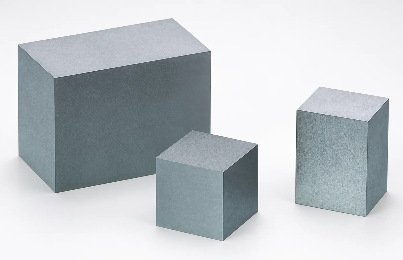
Various Steels Cavity Insert Block Blanks Reference Plane
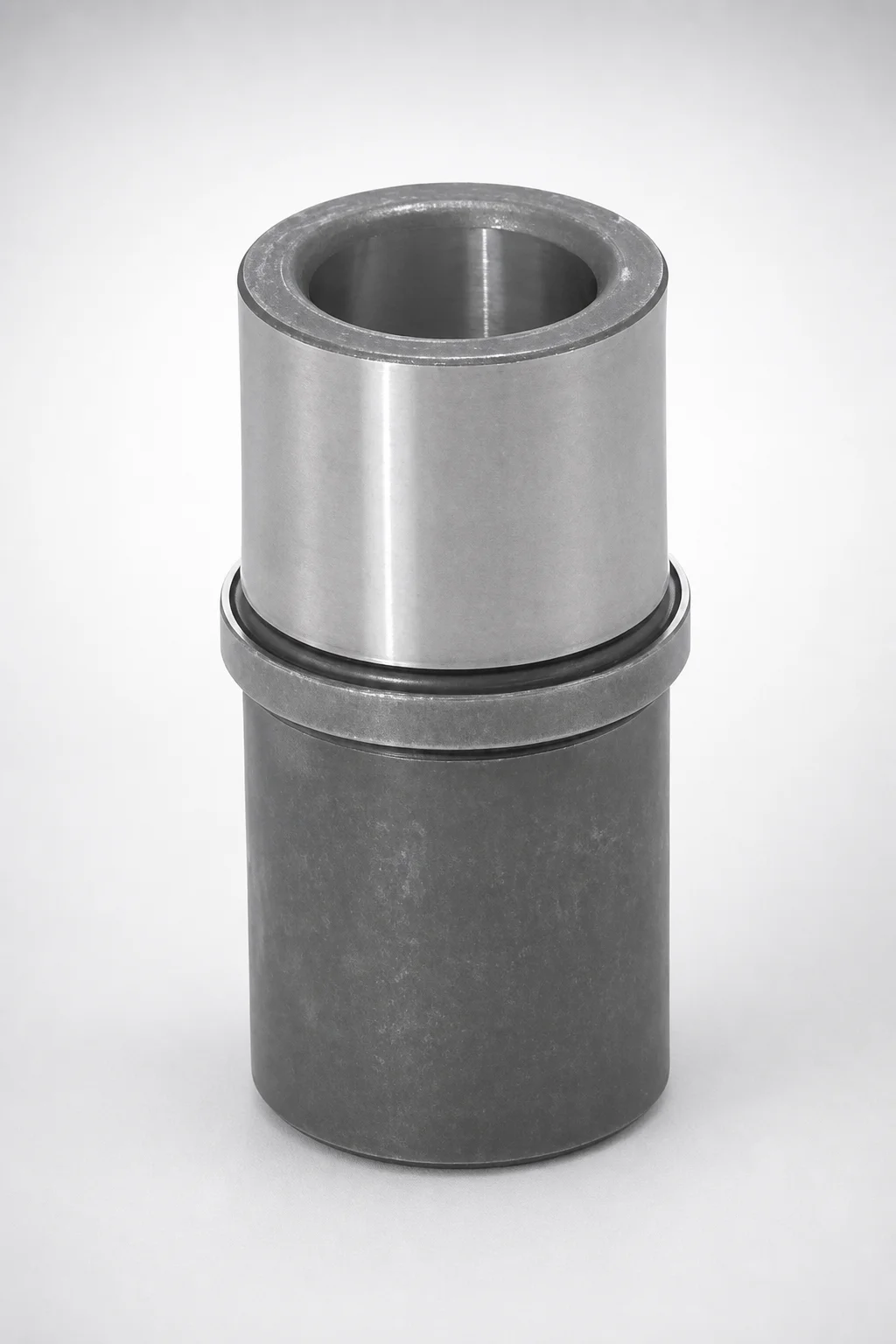
EGBN Type Ejector Leader Bushings Long Guide, Oil Grooves, SUJ2 Bearing Steel
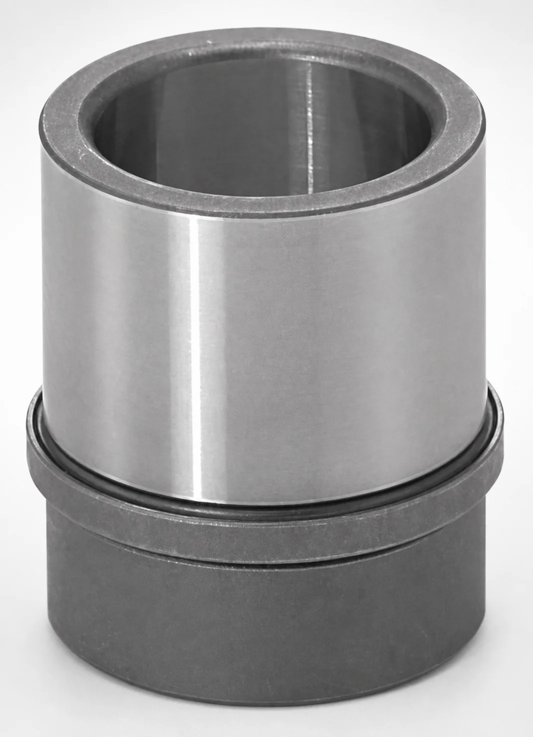
Ejector Leader Bushings - Oil Grooves SUJ2 Bearing Steel
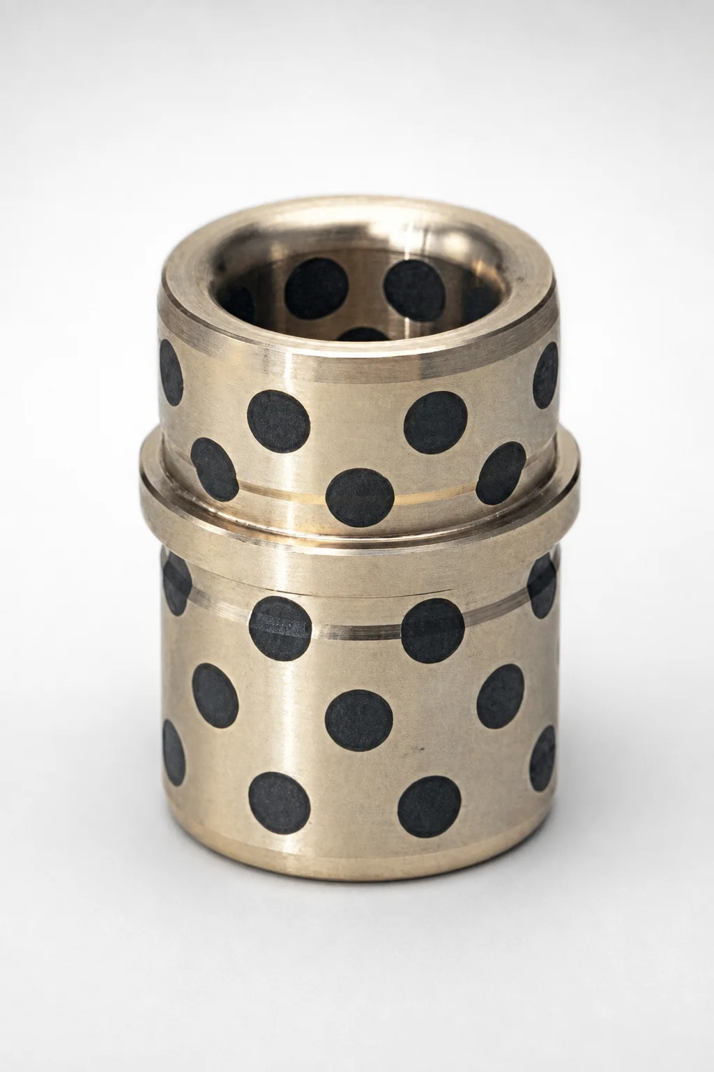
EGBZ Oil-Free Ejector Leader Bushings Long Guide
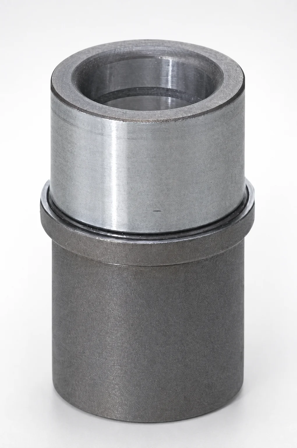
EGBNZ Type Oil-Free Ejector Leader Bushings Long Guide SUJ2 Bearing Steel
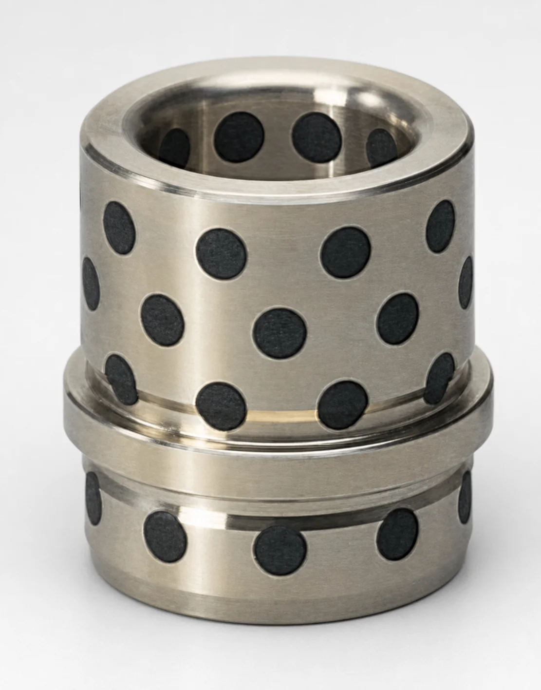
EGBZS Type Oil-Free Ejector Leader Bushings - Copper Alloy
Need Custom Specifications?
Our engineering team can help with custom configurations, material selection, and volume pricing.