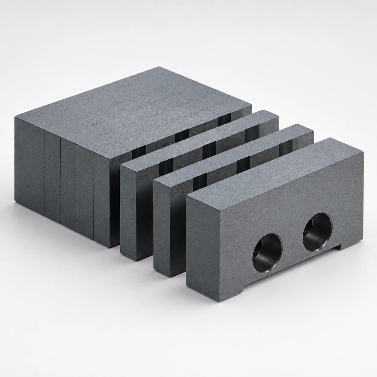
Gas Vent Cavity Inserts BGV
Gas vent cavity inserts BGV are designed to improve mold exhaust during molding by providing dedicated venting grooves where gas release is required. They help support stable cavity performance and consistent part quality.
- BGV cavity insert type supports controlled gas vent for better exhaust
- Built from robust hardening steel for wear resistance in mold service
- Optimized groove design for reliable venting performance under production cycles
- Used in cavity insert applications where gas vent efficiency is critical
Specifications
6 configurations available
| A (External shape) (mm) | B (External shape) (mm) | T (Thickness) (mm) | S (Grooves for gas release) (mm) | type |
|---|---|---|---|---|
| 40 | 40 | 40 | 0.03 ~ 0.05 | - |
| 40 | 50 | 40 | 0.03 ~ 0.05 | - |
| 40 | 60 | 40 | 0.03 ~ 0.05 | - |
| 80 | 60 | 80 | 0.03 ~ 0.05 | - |
| 80 | 70 | 80 | 0.03 ~ 0.05 | - |
| 80 | 80 | 80 | 0.03 ~ 0.05 | - |
Product Guide
Application Scenarios+
These gas vent cavity inserts are used in injection and die-casting mold tooling where controlled exhaust is critical to prevent air traps, burn marks, and surface defects. Install the insert into a cavity side or cavity block to create dedicated venting grooves that guide released gas away from the filling front.
In large-scale die-casting, the controlled groove section (with vent grooves sized in the 0.03–0.05 mm range) helps maintain stable cavity performance across production cycles by improving consistent mold exhaust. This is especially beneficial for parts with tight geometries or long flow paths where gas entrapment is more likely.
In thick-section or multi-feature cavity systems, pairing the insert with burr-cutting pin tooling areas can support repeatable surface finish by reducing trapped gases at sharp transitions. The hardening steel construction supports wear resistance in high-cycle service, helping the vent groove geometry remain functional over time.
Material & Process Details+
The BGV insert is specified as being made from hardening steel, selected to withstand the abrasive and cyclic contact conditions common in mold operation. Hardening steel provides good wear resistance for small vent groove features that must remain accurate during repetitive thermal cycling and clamping loads.
Heat treatment is not explicitly listed in the provided specifications, but “hardening steel” in this context indicates the component is produced for a hardened state suitable for mold service. Depending on the downstream process at the moldmaker, the insert is typically quenched and tempered after rough machining to balance hardness and toughness.
- Wear resistance: improved by hardening and tempering, helping protect fine groove surfaces.
- Toughness trade-off: higher hardness can reduce impact toughness; proper tempering is used to manage cracking risk.
- Hardness (HRC): not stated in the provided data—confirm with your MISUMI/BGV material certificate for exact HRC.
Sizing & Selection Guide+
Select the insert geometry by matching the external shape dimensions to the pocket or insert-mounting area in your mold cavity/core. The provided options include A (external shape) of 40 or 80 mm, and B (external shape) of 40, 50, 60, 70, or 80 mm, with T (thickness) of 40 or 80 mm.
Use the vent groove specification to confirm exhaust performance: the grooves for gas release are fixed at S = 0.03–0.05 mm. Ensure your cavity layout positions the vent feature at the expected gas-trap location (near the end of fill, around thick-to-thin transitions, or at likely air entrapment zones).
- Dimension matching: confirm your pocket depth accommodates the selected T, and that the external footprint clears neighboring cavity features.
- Tolerance/fit: the vent groove is a micro-feature; aim for controlled seating and stable contact surfaces so groove alignment is not distorted during tightening.
- Configurable vs fixed: A, B, T are configurable; S is fixed at 0.03–0.05 mm.
Frequently Asked Questions
What vent groove thickness (S) is available on the BGV gas vent cavity insert?+
The BGV insert specifies fixed S (grooves for gas release) = 0.03–0.05 mm. This range is intended to provide controlled exhaust and maintain venting effectiveness without excessively opening the cavity surface.
Which external shape dimensions can be selected for MISUMI BGV gas vent cavity inserts?+
You can select A (external shape) as 40 or 80 mm, B (external shape) as 40, 50, 60, 70, or 80 mm, and T (thickness) as 40 or 80 mm.
These dimensions should be matched to the mold pocket size to ensure correct seating and proper positioning of the vent grooves.
How should I position the insert in a die-casting cavity to reduce air traps?+
Position the vent grooves at locations where gas is expected to accumulate, such as near the end of fill or around thick-to-thin transitions. The controlled groove specification (S = 0.03–0.05 mm) is suited for improving exhaust stability and reducing surface defects driven by trapped gas.
Is the BGV insert material hardened steel, and what hardness should I expect (HRC)?+
The data describes the insert as being made from hardening steel for wear resistance in mold service. However, the provided specifications do not include an exact HRC value.
For hardness confirmation, request the material/certification sheet for the exact heat treatment condition used for this series code.
Do A, B, and T affect the vent performance, or is only S responsible for exhaust?+
S is the fixed vent groove parameter (0.03–0.05 mm), which directly defines the vent groove geometry. Meanwhile, A, B, and T primarily control how the insert fits and how the vent feature is positioned within the cavity pocket.
Incorrect fit or alignment can reduce effective venting even if S is within the intended range.
Related Products
Need Custom Specifications?
Our engineering team can help with custom configurations, material selection, and volume pricing.