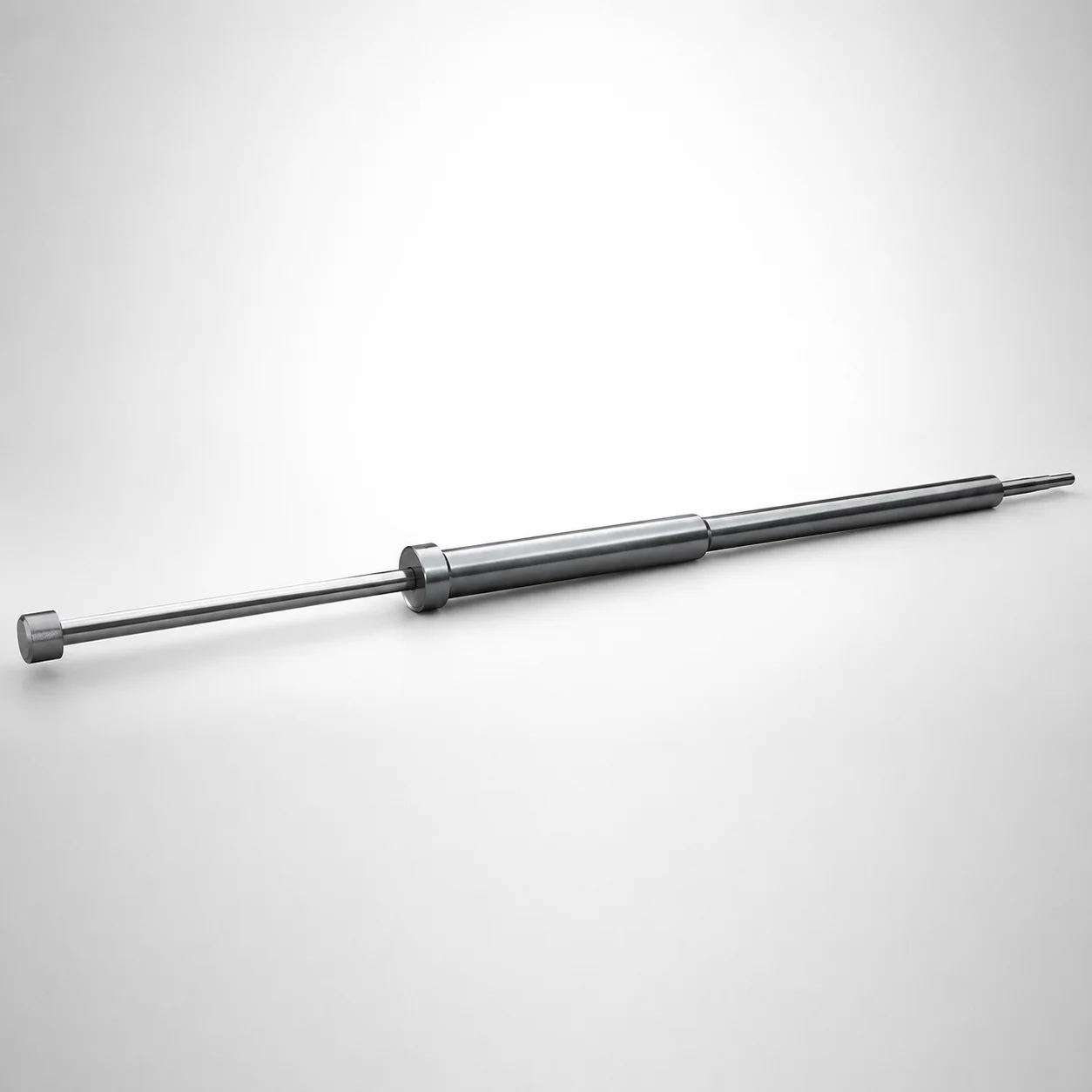
SKD61 Steel Stepped Ejector Sleeves & One-Step Center Pin Sets
Stepped ejector sleeves & one-step center pin sets (SKD61 steel) are engineered for precise alignment in mold ejection. The nitrided surface treatment supports consistent performance under repeated cycles.
- Stepped sleeve design improves concentric guidance for center pin sets
- Nitrided SKD61 hardened steel construction enhances wear resistance
- Controlled H7 inner diameter tolerance helps maintain stable assembly fit
- Concentricity target of 0.06 mm supports repeatable ejection accuracy
Specifications
110 configurations available
| Head Thickness | D (Shaft Diameter) (mm) | P (Tip Diameter) (mm) | V (Hole Diameter) (mm) | Center Pin Tip Shape | A (Center pin tip diameter) (mm) | C (Recess diameter) (mm) | E (Center pin tip diameter) (mm) | F (Center pin shaft diameter length) (mm) | L (L dimension) (mm) | Dimension N (mm) | Dimension R (mm) | S (V hole diameter length) (mm) | X (Full length of the center pin) (mm) | type |
|---|---|---|---|---|---|---|---|---|---|---|---|---|---|---|
| 6mm(JIS) | 5 | 3.5 ~ 4.95 | 2 ~ 3 | A | - | - | 1 ~ 3 | 50 ~ 349.5 | 50 ~ 250 | 17 ~ 249 | - | 20 ~ 100 | 70 ~ 350 | - |
| 6mm(JIS) | 5.5 | 3.5 ~ 5.45 | 2 ~ 3.5 | A | - | - | 1 ~ 3.49 | 50 ~ 349.5 | 50 ~ 250 | 17 ~ 248 | - | 20 ~ 100 | 70 ~ 350 | - |
| 6mm(JIS) | 6 | 4 ~ 5.95 | 2.5 ~ 4 | A | - | - | 1 ~ 3.99 | 100 ~ 399.5 | 80 ~ 300 | 27 ~ 298 | - | 20 ~ 100 | 70 ~ 400 | - |
| 6mm(JIS) | 6.5 | 4 ~ 6.45 | 2.5 ~ 4 | A | - | - | 1 ~ 3.99 | 50 ~ 399.5 | 80 ~ 300 | 27 ~ 398 | - | 20 ~ 100 | 100 ~ 400 | - |
| 6mm(JIS) | 7 | 4 ~ 6.95 | 2.5 ~ 4.5 | A | - | - | 1.5 ~ 4.49 | 50 ~ 399.5 | 80 ~ 300 | 27 ~ 299 | - | 20 ~ 100 | 100 ~ 400 | - |
| 6mm(JIS) | 7.5 | 4 ~ 7.45 | 2.5 ~ 4.5 | A | - | - | 1.5 ~ 4.49 | 50 ~ 399.5 | 80 ~ 300 | 27 ~ 299 | - | 20 ~ 100 | 100 ~ 400 | - |
| 8mm(JIS) | 8 | 5 ~ 7.95 | 2.5 ~ 5.5 | A | - | - | 2 ~ 5.49 | 50 ~ 399.5 | 80 ~ 300 | 27 ~ 299 | - | 30 ~ 100 | 100 ~ 400 | - |
| 8mm(JIS) | 10 | 6 ~ 9.95 | 4 ~ 7 | A | - | - | 2 ~ 6.99 | 50 ~ 399.5 | 80 ~ 300 | 27 ~ 299 | - | S | 100 ~ 399.5 | - |
| 8mm(JIS) | 10 | 6 ~ 9.95 | 4 ~ 7 | A | - | - | 2 ~ 6.99 | 50 ~ 399.5 | 80 ~ 300 | 27 ~ 299 | - | 30 ~ 100 | 100 ~ 399.5 | - |
| 8mm(JIS) | 12 | 7.5 ~ 11.95 | 4 ~ 8 | A | - | - | 2 ~ 7.99 | 50 ~ 399.5 | 80 ~ 300 | 27 ~ 299 | - | 30 ~ 100 | 100 ~ 400 | - |
| 6mm(JIS) | 5 | 3.5 ~ 4.95 | 2 ~ 3 | B | 1 ~ 2.99 | - | 1 ~ 2.99 | 50 ~ 349.5 | 50 ~ 250 | 17 ~ 249 | - | 20 ~ 100 | 70 ~ 350 | - |
| 6mm(JIS) | 5.5 | 3.5 ~ 5.45 | 2 ~ 3.5 | B | 1 ~ 3.49 | - | 1 ~ 3.49 | 50 ~ 349.5 | 50 ~ 250 | 17 ~ 248 | - | 20 ~ 100 | 70 ~ 350 | - |
| 6mm(JIS) | 6 | 4 ~ 5.95 | 2.5 ~ 4 | B | 1 ~ 3.99 | - | 1 ~ 3.99 | 100 ~ 399.5 | 80 ~ 300 | 27 ~ 298 | - | 20 ~ 100 | 70 ~ 400 | - |
| 6mm(JIS) | 6.5 | 4 ~ 6.45 | 2.5 ~ 4 | B | 1 ~ 3.99 | - | 1 ~ 3.99 | 50 ~ 399.5 | 80 ~ 300 | 27 ~ 398 | - | 20 ~ 100 | 100 ~ 400 | - |
| 6mm(JIS) | 7 | 4 ~ 6.95 | 2.5 ~ 4.5 | B | 1.5 ~ 4.49 | - | 1.5 ~ 4.49 | 50 ~ 399.5 | 80 ~ 300 | 27 ~ 299 | - | 20 ~ 100 | 100 ~ 400 | - |
| 6mm(JIS) | 7.5 | 4 ~ 7.45 | 2.5 ~ 4.5 | B | 1.5 ~ 4.49 | - | 1.5 ~ 4.49 | 50 ~ 399.5 | 80 ~ 300 | 27 ~ 299 | - | 20 ~ 100 | 100 ~ 400 | - |
| 8mm(JIS) | 8 | 5 ~ 7.95 | 2.5 ~ 5.5 | B | 2 ~ 5.49 | - | 2 ~ 5.49 | 50 ~ 399.5 | 80 ~ 300 | 27 ~ 299 | - | 30 ~ 100 | 100 ~ 400 | - |
| 8mm(JIS) | 10 | 6 ~ 9.95 | 4 ~ 7 | B | 2 ~ 6.99 | - | 2 ~ 6.99 | 50 ~ 399.5 | 80 ~ 300 | 27 ~ 299 | - | 30 ~ 100 | 100 ~ 400 | - |
| 8mm(JIS) | 12 | 7.5 ~ 11.95 | 4 ~ 8 | B | 2 ~ 7.99 | - | 2 ~ 7.99 | 50 ~ 399.5 | 80 ~ 300 | 27 ~ 299 | - | 30 ~ 100 | 100 ~ 400 | - |
| 6mm(JIS) | 5 | 3.5 ~ 4.95 | 2 ~ 3 | C | 1 ~ 2.99 | - | 1 ~ 2.99 | 50 ~ 349.5 | 50 ~ 250 | 17 ~ 249 | - | 20 ~ 100 | 70 ~ 350 | - |
| 6mm(JIS) | 5.5 | 3.5 ~ 5.45 | 2 ~ 3.5 | C | 1 ~ 3.49 | - | 1 ~ 3.49 | 50 ~ 349.5 | 50 ~ 250 | 17 ~ 248 | - | 20 ~ 100 | 70 ~ 350 | - |
| 6mm(JIS) | 6 | 4 ~ 5.95 | 2.5 ~ 4 | C | 1 ~ 3.99 | - | 1 ~ 3.99 | 100 ~ 399.5 | 80 ~ 300 | 27 ~ 298 | - | 20 ~ 100 | 70 ~ 400 | - |
| 6mm(JIS) | 6.5 | 4 ~ 6.45 | 2.5 ~ 4 | C | 1 ~ 3.99 | - | 1 ~ 3.99 | 50 ~ 399.5 | 80 ~ 300 | 27 ~ 398 | - | 20 ~ 100 | 100 ~ 400 | - |
| 6mm(JIS) | 7 | 4 ~ 6.95 | 2.5 ~ 4.5 | C | 1.5 ~ 4.49 | - | 1.5 ~ 4.49 | 50 ~ 399.5 | 80 ~ 300 | 27 ~ 299 | - | 20 ~ 100 | 100 ~ 400 | - |
| 6mm(JIS) | 7.5 | 4 ~ 7.45 | 2.5 ~ 4.5 | C | 1.5 ~ 4.49 | - | 1.5 ~ 4.49 | 50 ~ 399.5 | 80 ~ 300 | 27 ~ 299 | - | 20 ~ 100 | 100 ~ 400 | - |
| 8mm(JIS) | 8 | 5 ~ 7.95 | 2.5 ~ 5.5 | C | 2 ~ 5.49 | - | 2 ~ 5.49 | 50 ~ 399.5 | 80 ~ 300 | 27 ~ 299 | - | 30 ~ 100 | 100 ~ 400 | - |
| 8mm(JIS) | 10 | 6 ~ 9.95 | 4 ~ 7 | C | 2 ~ 6.99 | - | 2 ~ 6.99 | 50 ~ 399.5 | 80 ~ 300 | 27 ~ 299 | - | 30 ~ 100 | 100 ~ 400 | - |
| 8mm(JIS) | 12 | 7.5 ~ 11.95 | 4 ~ 8 | C | 2 ~ 7.99 | - | 2 ~ 7.99 | 50 ~ 399.5 | 80 ~ 300 | 27 ~ 299 | - | 30 ~ 100 | 100 ~ 400 | - |
| 6mm(JIS) | 5 | 3.5 ~ 4.95 | 2 ~ 3 | D | 1 ~ 2.99 | 0.1 ~ 1 | 1 ~ 2.99 | 50 ~ 349.5 | 50 ~ 250 | 17 ~ 249 | - | 20 ~ 100 | 70 ~ 350 | - |
| 6mm(JIS) | 5.5 | 3.5 ~ 5.45 | 2 ~ 3.5 | D | 1 ~ 3.49 | 0.1 ~ 1 | 1 ~ 3.49 | 50 ~ 349.5 | 50 ~ 250 | 17 ~ 248 | - | 20 ~ 100 | 70 ~ 350 | - |
| 6mm(JIS) | 6 | 4 ~ 5.95 | 2.5 ~ 4 | D | 1 ~ 3.99 | 0.3 ~ 1 | 1 ~ 3.99 | 100 ~ 399.5 | 80 ~ 300 | 27 ~ 298 | - | 20 ~ 100 | 70 ~ 400 | - |
| 6mm(JIS) | 6.5 | 4 ~ 6.45 | 2.5 ~ 4 | D | 1 ~ 3.99 | 0.3 ~ 1 | 1 ~ 3.99 | 50 ~ 399.5 | 80 ~ 300 | 27 ~ 398 | - | 20 ~ 100 | 100 ~ 400 | - |
| 6mm(JIS) | 7 | 4 ~ 6.95 | 2.5 ~ 4.5 | D | 1.5 ~ 4.49 | 0.3 ~ 1 | 1.5 ~ 4.49 | 50 ~ 399.5 | 80 ~ 300 | 27 ~ 299 | - | 20 ~ 100 | 100 ~ 400 | - |
| 6mm(JIS) | 7.5 | 4 ~ 7.45 | 2.5 ~ 4.5 | D | 1.5 ~ 4.49 | 0.3 ~ 1 | 1.5 ~ 4.49 | 50 ~ 399.5 | 80 ~ 300 | 27 ~ 299 | - | 20 ~ 100 | 100 ~ 400 | - |
| 8mm(JIS) | 8 | 5 ~ 7.95 | 2.5 ~ 5.5 | D | 2 ~ 5.49 | 0.1 ~ 1.5 | 2 ~ 5.49 | 50 ~ 399.5 | 80 ~ 300 | 27 ~ 299 | - | 30 ~ 100 | 100 ~ 400 | - |
| 8mm(JIS) | 10 | 6 ~ 9.95 | 4 ~ 7 | D | 2 ~ 6.99 | 0.1 ~ 1 | 2 ~ 6.99 | 50 ~ 399.5 | 80 ~ 300 | 27 ~ 299 | - | 30 ~ 100 | 100 ~ 400 | - |
| 8mm(JIS) | 12 | 7.5 ~ 11.95 | 4 ~ 8 | D | 2 ~ 7.99 | 0.3 ~ 1 | 2 ~ 7.99 | 50 ~ 399.5 | 80 ~ 300 | 27 ~ 299 | - | 30 ~ 100 | 100 ~ 400 | - |
| 6mm(JIS) | 5 | 3.5 ~ 4.95 | 2 ~ 3 | E | 1 ~ 2.99 | - | 1 ~ 2.99 | 50 ~ 349.5 | 50 ~ 250 | 17 ~ 249 | 0.3 ~ 5 | 20 ~ 100 | 70 ~ 350 | - |
| 6mm(JIS) | 5.5 | 3.5 ~ 5.45 | 2 ~ 3.5 | E | 1 ~ 3.49 | - | 1 ~ 3.49 | 50 ~ 349.5 | 50 ~ 250 | 17 ~ 248 | 0.3 ~ 5 | 20 ~ 100 | 70 ~ 350 | - |
| 6mm(JIS) | 6 | 4 ~ 5.95 | 2.5 ~ 4 | E | 1 ~ 3.99 | - | 1 ~ 3.99 | 100 ~ 399.5 | 80 ~ 300 | 27 ~ 298 | 0.3 ~ 5 | 20 ~ 100 | 70 ~ 400 | - |
| 6mm(JIS) | 6.5 | 4 ~ 6.45 | 2.5 ~ 4 | E | 1 ~ 3.99 | - | 1 ~ 3.99 | 50 ~ 399.5 | 80 ~ 300 | 27 ~ 398 | 0.3 ~ 5 | 20 ~ 100 | 100 ~ 400 | - |
| 6mm(JIS) | 7 | 4 ~ 6.95 | 2.5 ~ 4.5 | E | 1.5 ~ 4.49 | - | 1.5 ~ 4.49 | 50 ~ 399.5 | 80 ~ 300 | 27 ~ 299 | 0.3 ~ 5 | 20 ~ 100 | 100 ~ 400 | - |
| 6mm(JIS) | 7.5 | 4 ~ 7.45 | 2.5 ~ 4.5 | E | 1.5 ~ 4.49 | - | 1.5 ~ 4.49 | 50 ~ 399.5 | 80 ~ 300 | 27 ~ 299 | 0.3 ~ 5 | 20 ~ 100 | 100 ~ 400 | - |
| 8mm(JIS) | 8 | 5 ~ 7.95 | 2.5 ~ 5.5 | E | 2 ~ 5.49 | - | 2 ~ 5.49 | 50 ~ 399.5 | 80 ~ 300 | 27 ~ 299 | 0.3 ~ 5 | 30 ~ 100 | 100 ~ 400 | - |
| 8mm(JIS) | 10 | 6 ~ 9.95 | 4 ~ 7 | E | 2 ~ 6.99 | - | 2 ~ 6.99 | 50 ~ 399.5 | 80 ~ 300 | 27 ~ 299 | 0.3 ~ 5 | 30 ~ 100 | 100 ~ 400 | - |
| 8mm(JIS) | 12 | 7.5 ~ 11.95 | 4 ~ 8 | E | 2 ~ 7.99 | - | 2 ~ 7.99 | 50 ~ 399.5 | 80 ~ 300 | 27 ~ 299 | 0.3 ~ 5 | 30 ~ 100 | 100 ~ 400 | - |
| 6mm(JIS) | 5 | 3.5 ~ 4.95 | 2 ~ 3 | S | - | - | - | - | 50 ~ 250 | 17 ~ 249 | - | 20 ~ 100 | 70 ~ 350 | - |
| 6mm(JIS) | 5.5 | 3.5 ~ 5.45 | 2 ~ 3.5 | S | - | - | - | - | 50 ~ 250 | 17 ~ 248 | - | 20 ~ 100 | 70 ~ 350 | - |
| 6mm(JIS) | 6 | 4 ~ 5.95 | 2.5 ~ 4 | S | - | - | - | - | 80 ~ 300 | 27 ~ 298 | - | 20 ~ 100 | 70 ~ 400 | - |
| 6mm(JIS) | 6.5 | 4 ~ 6.45 | 2.5 ~ 4 | S | - | - | - | - | 80 ~ 300 | 27 ~ 398 | - | 20 ~ 100 | 100 ~ 400 | - |
Product Guide
Application Scenarios+
Stepped ejector sleeves and one-step center pin sets are used in precision injection mold ejection systems where repeatable alignment is critical. In automotive connector and small housing molds, the stepped sleeve guides the center pin to reduce lateral play during ejection. The nitrided SKD61 variant helps maintain stable wear performance under high cycle counts, supporting consistent ejection accuracy.
- Medical device housings: uses tight inner diameter fit (e.g., H7) to stabilize alignment and support fine tolerances in pin-assisted ejection.
- Consumer electronics enclosures: the concentricity target (0.06 mm) improves concentric guidance for reliable part release of flat or thin-wall components.
For each scenario, the stepped geometry improves concentric guidance of the center pin set, while the nitrided surface improves resistance to sliding wear and helps preserve function over repeated ejection cycles.
Material & Process Details+
This product uses SKD61 tool steel for stepped ejector sleeves and center pins. SKD61 corresponds to the widely used H13 (AISI/ASTM H13) class of hot-work tool steels, offering a balance of strength and wear resistance for mold tooling applications.
- Heat treatment state: nitrided surface treatment is specified to improve near-surface hardness and wear resistance while the steel core retains toughness.
- Wear resistance vs. toughness: nitriding increases surface durability for sliding contact during ejection, while the tempered steel core supports resistance to cracking under cyclic loading.
- Hardness (HRC): hardness values are not provided in the supplied specification data; final HRC should be confirmed for the exact size/heat lot when qualifying for your press conditions.
If an alternative is considered, the key trade-off is typically surface hardness and scuff resistance (improved by nitriding) versus bulk toughness and machinability (dependent on quench & temper practice).
Sizing & Selection Guide+
Select the center pin and stepped sleeve dimensions by matching the shaft and tip geometry to your ejector layout and cavity/core features. Start with D (shaft diameter) in the range 5 ~ 12 mm, and choose the corresponding P (tip diameter) from 3.5 ~ 7.5 mm. For the mating bore, use V (hole diameter) of 2 ~ 4 mm and the center pin tip shape code (A, B, C, D, E, S), ensuring the tip profile matches the recess geometry.
- For the center pin tip, confirm A (1 ~ 2 mm) or E (1 ~ 2 mm) as specified for your selected tip shape.
- Match recess diameter C, noting multiple ranges (e.g., 0.1 ~ 1, 0.3 ~ 1, 0.1 ~ 1.5, 0.2 ~ 1).
- Verify overall lengths: F (shaft diameter length) ranges 50 ~ 349.5 or 100 ~ 399.5 depending on configuration; L is 50 ~ 250 or 80 ~ 300 mm, and X (full length) ranges up to 70 ~ 400 mm (configuration dependent).
Assembly fit references include an H7 inner diameter tolerance for the sleeve; maintain the intended clearance/interference for stable guidance. If choosing head thickness, use 6 mm (JIS), 8 mm (JIS), or 4 mm (T4) as applicable. Dimension R (0.3 ~ 5 mm) should be checked for feature radius compatibility; it is fixed by the selected size.
Frequently Asked Questions
How do I choose the correct sleeve inner diameter tolerance for stable pin alignment?+
The stepped ejector sleeve set is specified with a controlled H7 inner diameter tolerance to maintain stable assembly fit. When designing the mating bore in the mold block, ensure the bore size and tolerance class are coordinated with this H7 guidance requirement to minimize play during repeated ejection.
What dimensions should I match first to ensure the stepped sleeve and one-step center pin set work together concentrically?+
Begin by matching D (shaft diameter 5 ~ 12 mm) and P (tip diameter 3.5 ~ 7.5 mm). Then select the proper center pin tip shape (A, B, C, D, E, S) and verify recess/hole-related sizes such as V (2 ~ 4 mm) and C (multiple ranges provided). The product includes a concentricity target of 0.06 mm, which depends on choosing the correct geometry and length combination.
How does the nitrided SKD61 surface treatment affect wear for ejection cycles?+
The material is SKD61 with a nitrided surface, designed to improve wear resistance in sliding contact during ejection. This helps preserve the guidance function over repeated cycles. Exact surface hardness/HRC after nitriding is not listed in the provided specification data, so confirm values for your qualification requirements.
Can I use the same part family for different ejector lengths, and which length parameters must be checked?+
Yes—this family supports multiple length configurations via F (shaft diameter length 50 ~ 349.5 or 100 ~ 399.5 depending on configuration), L (50 ~ 250 or 80 ~ 300 mm), and X (full center pin length 70 ~ 350, 70 ~ 400, 100 ~ 400, or 100 ~ 399.5 mm depending on variant). Ensure the selected head thickness matches (6 mm JIS, 8 mm JIS, or 4 mm T4) so the assembly stack height remains correct.
What is the role of dimension R and which parameters are fixed vs. configurable?+
Dimension R is listed as a fixed range (0.3 ~ 5 mm) tied to the selected size configuration. In contrast, key dimensions are configurable within specified ranges, including D (5 ~ 12 mm), P (3.5 ~ 7.5 mm), V (2 ~ 4 mm), A, C, E, and lengths F, L, and X. Match the configurable values to your mold cavity/core geometry while keeping the fixed R consistent with the chosen variant.
Related Products
Need Custom Specifications?
Our engineering team can help with custom configurations, material selection, and volume pricing.