Stepped Ejector Sleeve Components
Stepped hollow sleeves designed to minimize surface contact with mold core plates, drastically reducing sliding wear on long ejector stroke travels.
Product Categories
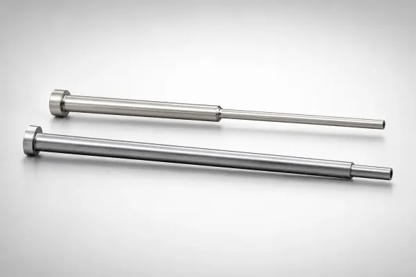
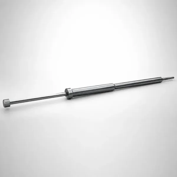
Selection Matrix: Straight vs. Stepped Sleeves
Understand the structural and operational differences between straight and stepped sleeve geometries:
| Design Feature | Straight Sleeves | Stepped Sleeves |
|---|---|---|
| Contact Length | Full shaft length contact (high surface friction) | Limited to guide shoulder length (low friction) |
| Column Stiffness | Standard (susceptible to buckling on long stroke) | Enhanced (larger base diameter resists buckling) |
| Machining Effort | Low (single straight hole drilled in plates) | Medium (requires stepped guide hole boring) |
Decision rule: Use straight sleeves unless your mold plate configuration requires a diameter transition. Stepped sleeves cost more and have a fatigue-limited shoulder. For details on shoulder failure prevention, see our shoulder breakage analysis guide.
Receiver Hole Tolerancing Guidelines
Standard clearance values for stepped sleeve guide holes bored into core templates:
Frequently Asked Questions
How does a stepped ejector sleeve reduce friction in mold plates?+
What are the key design rules for stepped sleeve installation holes?+
Why do stepped sleeves have higher load capacity compared to straight sleeves?+
About Stepped Ejector Sleeve Components
Stepped ejector sleeve components feature a larger rear guide diameter and a smaller front molding diameter. This design reduces plate contact area and sliding friction, while providing higher column stiffness to resist buckling under heavy ejection loads. Ideal for long-stroke ejection applications and deep-cavity molds where straight sleeves would lack sufficient rigidity.
Engineering Resources
Need a Custom Quote?
Specify the step diameters (D/d), shoulder length, and total length for your stepped ejector sleeve or set. Custom step ratios available for non-standard mold plate thicknesses.