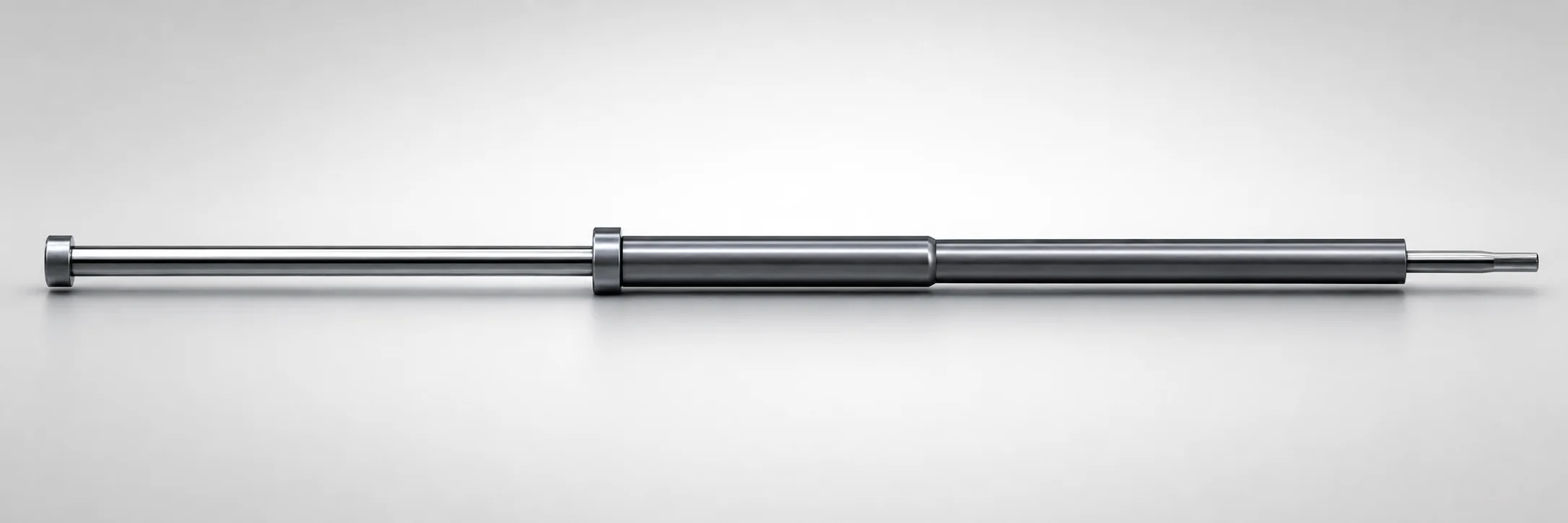
SKD61 Steel Stepped Ejector Sleeves & One-Step Center Pin Sets
Stepped ejector sleeves & one-step center pin sets (SKD61 steel) deliver accurate positioning for mold assembly and ejection, with a nitrided surface that supports stable long-term performance in production.
- Stepped sleeve geometry with one-step center pin configuration for repeatable alignment
- SKD61 steel build with nitrided surface treatment to improve wear resistance
- H7 inner diameter tolerance helps meet fit requirements for precise mold components
- Designed as center pin sets for press tooling using concentricity control around 0.06
Specifications
36 configurations available
| Head Thickness | D (Shaft Diameter) (mm) | V (Hole Diameter) (mm) | Center Pin Tip Shape | A (Center pin tip diameter) (mm) | C (Recess diameter) (mm) | E (Center pin tip diameter) (mm) | F (Center pin shaft diameter length) (mm) | L (L dimension) (mm) | Dimension N (mm) | Dimension R (mm) | X (Full length of the center pin) (mm) | type |
|---|---|---|---|---|---|---|---|---|---|---|---|---|
| 8mm(JIS) | 8 | 3.5 ~ 4.5 | A | - | - | 2 ~ 4.4 | 100 ~ 215 | 100 ~ 250 | 60 ~ 150 | - | 120 ~ 350 | - |
| 8mm(JIS) | 12 | 5 ~ 5.5 | A | - | - | 2 ~ 5.4 | 100 ~ 250 | 125 ~ 300 | 60 ~ 150 | - | 145 ~ 400 | - |
| 8mm(JIS) | 8 | 3.5 ~ 4.5 | B | 2 ~ 4.4 | - | 2 ~ 4.4 | 100 ~ 215 | 100 ~ 250 | 60 ~ 150 | - | 120 ~ 350 | - |
| 8mm(JIS) | 12 | 5 ~ 5.5 | B | 2 ~ 5.4 | - | 2 ~ 5.4 | 100 ~ 250 | 125 ~ 300 | 60 ~ 150 | - | 145 ~ 400 | - |
| 8mm(JIS) | 8 | 3.5 ~ 4.5 | C | 2 ~ 4.4 | - | 2 ~ 4.4 | 100 ~ 215 | 100 ~ 250 | 60 ~ 150 | - | 120 ~ 350 | - |
| 8mm(JIS) | 12 | 5 ~ 5.5 | C | 2 ~ 5.4 | - | 2 ~ 5.4 | 100 ~ 250 | 125 ~ 300 | 60 ~ 150 | - | 145 ~ 400 | - |
| 8mm(JIS) | 8 | 3.5 ~ 4.5 | D | 2 ~ 4.4 | 0.1 ~ 1.5 | 2 ~ 4.4 | 100 ~ 315 | 100 ~ 250 | 60 ~ 150 | - | 120 ~ 350 | - |
| 8mm(JIS) | 12 | 5 ~ 5.5 | D | 2 ~ 5.4 | 0.1 ~ 1.5 | 2 ~ 5.4 | 100 ~ 250 | 125 ~ 300 | 60 ~ 150 | - | 145 ~ 400 | - |
| 8mm(JIS) | 8 | 3.5 ~ 4.5 | E | 2 ~ 4.4 | - | 2 ~ 4.4 | 100 ~ 215 | 100 ~ 250 | 60 ~ 150 | 0.3 ~ 1.2 | 120 ~ 350 | - |
| 8mm(JIS) | 12 | 5 ~ 5.5 | E | 2 ~ 5.4 | - | 2 ~ 5.4 | 100 ~ 250 | 125 ~ 300 | 60 ~ 150 | 0.3 ~ 1.7 | 145 ~ 400 | - |
| 8mm(JIS) | 8 | 3.5 ~ 4.5 | S | - | - | - | - | 100 ~ 250 | 60 ~ 150 | - | 120 ~ 350 | - |
| 8mm(JIS) | 12 | 5 ~ 5.5 | S | - | - | - | - | 125 ~ 300 | 60 ~ 150 | - | 145 ~ 400 | - |
| 4mm(T4) | 4 | 2 | A | - | - | 0.7 ~ 1.99 | 100 ~ 172 | 100 ~ 150 | 50 ~ 80 | - | 120 ~ 250 | - |
| 4mm(T4) | 5 | 2 ~ 2.5 | A | - | - | 1 ~ 2.4 | 100 ~ 130 | 100 ~ 150 | 50 ~ 80 | - | 120 ~ 250 | - |
| 4mm(T4) | 6 | 2 ~ 3.5 | A | - | - | 1 ~ 3.4 | 100 ~ 225 | 100 ~ 250 | 60 ~ 100 | - | 120 ~ 350 | - |
| 4mm(T4) | 8 | 3.5 ~ 4.5 | A | - | - | 2 ~ 4.4 | 100 ~ 235 | 100 ~ 250 | 60 ~ 100 | - | 120 ~ 350 | - |
| 4mm(T4) | 4 | 2 | B | 0.7 ~ 1.99 | - | 0.7 ~ 1.99 | 100 ~ 130 | 100 ~ 150 | 50 ~ 80 | - | 120 ~ 250 | - |
| 4mm(T4) | 5 | 2 ~ 2.5 | B | 1 ~ 2.4 | - | 1 ~ 2.4 | 100 ~ 249.3 | 100 ~ 150 | 50 ~ 80 | - | 120 ~ 250 | - |
| 4mm(T4) | 6 | 2 ~ 3.5 | B | 1 ~ 3.4 | - | 1 ~ 3.4 | 100 ~ 330 | 100 ~ 250 | 60 ~ 100 | - | 120 ~ 350 | - |
| 4mm(T4) | 8 | 3.5 ~ 4.5 | B | 2 ~ 4.4 | - | 2 ~ 4.4 | 100 ~ 215 | 100 ~ 250 | 60 ~ 100 | - | 120 ~ 350 | - |
| 4mm(T4) | 4 | 2 | C | 0.7 ~ 1.99 | - | 0.7 ~ 1.99 | 100 ~ 130 | 100 ~ 150 | 50 ~ 80 | - | 120 ~ 250 | - |
| 4mm(T4) | 5 | 2 ~ 2.5 | C | 1 ~ 2.4 | - | 1 ~ 2.4 | 100 ~ 130 | 100 ~ 150 | 50 ~ 80 | - | 120 ~ 250 | - |
| 4mm(T4) | 6 | 2 ~ 3.5 | C | 1 ~ 3.4 | - | 1 ~ 3.4 | 100 ~ 225 | 100 ~ 250 | 60 ~ 100 | - | 120 ~ 350 | - |
| 4mm(T4) | 8 | 3.5 ~ 4.5 | C | 2 ~ 4.4 | - | 2 ~ 4.4 | 100 ~ 215 | 100 ~ 250 | 60 ~ 100 | - | 120 ~ 350 | - |
| 4mm(T4) | 4 | 2 | D | 0.7 ~ 1.99 | 0.1 ~ 1.5 | 0.7 ~ 1.99 | 100 ~ 248.5 | 100 ~ 150 | 50 ~ 80 | - | 120 ~ 250 | - |
| 4mm(T4) | 5 | 2 ~ 2.5 | D | 1 ~ 2.4 | 0.1 ~ 1.5 | 1 ~ 2.4 | 100 ~ 130 | 100 ~ 150 | 50 ~ 80 | - | 120 ~ 250 | - |
| 4mm(T4) | 6 | 2 ~ 3.5 | D | 1 ~ 3.4 | 0.1 ~ 1.5 | 1 ~ 3.4 | 100 ~ 225 | 100 ~ 250 | 60 ~ 100 | - | 120 ~ 350 | - |
| 4mm(T4) | 8 | 3.5 ~ 4.5 | D | 2 ~ 4.4 | 0.1 ~ 1.5 | 2 ~ 4.4 | 100 ~ 215 | 100 ~ 250 | 60 ~ 100 | - | 120 ~ 350 | - |
| 4mm(T4) | 4 | 2 | E | 0.7 ~ 1.99 | - | 0.7 ~ 1.99 | 100 ~ 130 | 100 ~ 150 | 50 ~ 80 | 0.3 ~ 0.6 | 120 ~ 250 | - |
| 4mm(T4) | 5 | 2 ~ 2.5 | E | 1 ~ 2.4 | - | 1 ~ 2.4 | 100 ~ 130 | 100 ~ 150 | 50 ~ 80 | 0.3 ~ 0.7 | 120 ~ 250 | - |
| 4mm(T4) | 6 | 2 ~ 3.5 | E | 1 ~ 3.4 | - | 1 ~ 3.4 | 100 ~ 225 | 100 ~ 250 | 60 ~ 100 | 0.3 ~ 1.2 | 120 ~ 350 | - |
| 4mm(T4) | 8 | 3.5 ~ 4.5 | E | 2 ~ 4.4 | - | 2 ~ 4.4 | 100 ~ 349 | 100 ~ 250 | 60 ~ 100 | 0.3 ~ 1.2 | 120 ~ 350 | - |
| 4mm(T4) | 4 | 2 | S | - | - | - | - | 100 ~ 150 | 50 ~ 80 | - | 120 ~ 250 | - |
| 4mm(T4) | 5 | 2 ~ 2.5 | S | - | - | - | - | 100 ~ 150 | 50 ~ 80 | - | 120 ~ 250 | - |
| 4mm(T4) | 6 | 2 ~ 3.5 | S | - | - | - | - | 100 ~ 250 | 60 ~ 100 | - | 120 ~ 350 | - |
| 4mm(T4) | 8 | 3.5 ~ 4.5 | S | - | - | - | - | 100 ~ 250 | 60 ~ 100 | - | 120 ~ 350 | - |
Product Guide
Application Scenarios+
These stepped ejector sleeve and one-step center pin sets are used in injection mold tooling where repeatable component alignment between stationary mold halves and moving assemblies is critical. The stepped sleeve geometry supports controlled positioning during clamping, while the one-step center pin configuration helps maintain consistent engagement across cycles—reducing the risk of misalignment-driven wear.
- Automotive connector and sensor housings: When fine features require stable ejection and consistent parting, the nitrided SKD61 surface is suited to high-cycle production where sliding contact can accelerate wear.
- Consumer electronics and multi-cavity parts: For molds with multiple cavities and frequent starts/stops, the H7 inner diameter tolerance supports a precise fit for reliable stack-up control.
- Industrial appliance housings: In long ejection stroke tooling, the stepped design improves guidance, helping the pin set stay centered and protect mating surfaces.
Material & Process Details+
This product uses SKD61 steel, commonly selected for hot and wear-prone mold components due to its balance of hardness and toughness. With a nitrided surface treatment, the near-surface layer gains improved wear resistance while the core retains sufficient toughness to handle ejection impacts.
- Wear resistance: Nitriding forms a hard surface layer that better resists abrasion from sleeve-to-pin sliding contact.
- Toughness trade-off: Because nitriding primarily strengthens the surface, the part still relies on the SKD61 core’s toughness for resistance to chipping under cyclic loading.
- Heat treatment state: Supplied with nitrided surface treatment for durable long-term performance; bulk condition is based on SKD61’s standard mold steel heat treatment practice.
Material comparison: Compared with through-hardened wear steels, nitriding offers strong surface protection with less risk of brittleness spreading into the core.
Sizing & Selection Guide+
Select the sleeve and center pin set by matching the shaft and hole dimensions to your mold’s core/cavity stack-up. The product provides shaft diameter (D) options at 4, 5, 6, 8, and 12 mm, and the hole diameter (V) is available across ranges including 3.5–4.5, 5–5.5, 2, 2–2.5, and 2–3.5 mm.
- Step 1: Fit to mating features: Use the specified H7 inner diameter tolerance as your key fit reference. Choose the D/V pair that matches your sleeve bore and pin sizing requirements for stable guidance.
- Step 2: Length match: Center pin L is offered in 100–250, 125–300, and 100–150 mm ranges; full pin length X is available at 120–350, 145–400, and 120–250 mm.
- Step 3: Alignment stability: Confirm recess diameter C = 0.1–1.5 mm and center pin tip shape (A/B/C/D/E/S) to achieve the designed engagement geometry.
For best concentricity around the intended stack-up, maintain the same tolerance philosophy used by the mold’s guiding system; treat H7 guidance as the primary precision constraint.
Frequently Asked Questions
How does the SKD61 nitrided surface treatment influence wear for ejector sleeve and one-step center pin use?+
The set is supplied with a nitrided surface treatment, which improves wear resistance at the sliding contact zone between the stepped ejector sleeve and the center pin. In production molds with repeated ejection cycles, this helps maintain stable guidance geometry over time.
What inner diameter tolerance should be used when designing the mating bore for this component?+
The product description specifies H7 inner diameter tolerance. When defining the mating bore, apply H7-based sizing to achieve the intended fit and guidance repeatability with the chosen D (shaft diameter) option.
Which shaft diameter (D) options and corresponding hole diameter (V) ranges are available for design selection?+
The shaft diameter D is available at 4, 5, 6, 8, and 12 mm. Hole diameter V is offered in multiple ranges: 3.5–4.5, 5–5.5, 2, 2–2.5, and 2–3.5 mm. Select the D/V combination that matches your guidance clearance and stack-up requirements.
How do I choose the correct center pin length (L vs. full length X) for my mold assembly?+
The specification lists L ranges of 100–250, 125–300, and 100–150 mm, and a full length X range of 120–350, 145–400, and 120–250 mm. Choose L to match the effective guided engagement, and confirm X to ensure correct overall projection within the mold opening/closing stroke.
What center pin tip shape and diameter ranges can be selected to match engagement geometry?+
Center pin tip shape options include A, B, C, D, E, and S. The corresponding center pin tip diameter ranges (listed for A/E in the data) span multiple sets including 2–4.4, 2–5.4, 0.7–1.99, 1–2.4, and 1–3.4 mm, depending on the chosen configuration. Validate the selected tip diameter against your recess diameter C (0.1–1.5 mm) and required engagement.
Related Products
Need Custom Specifications?
Our engineering team can help with custom configurations, material selection, and volume pricing.