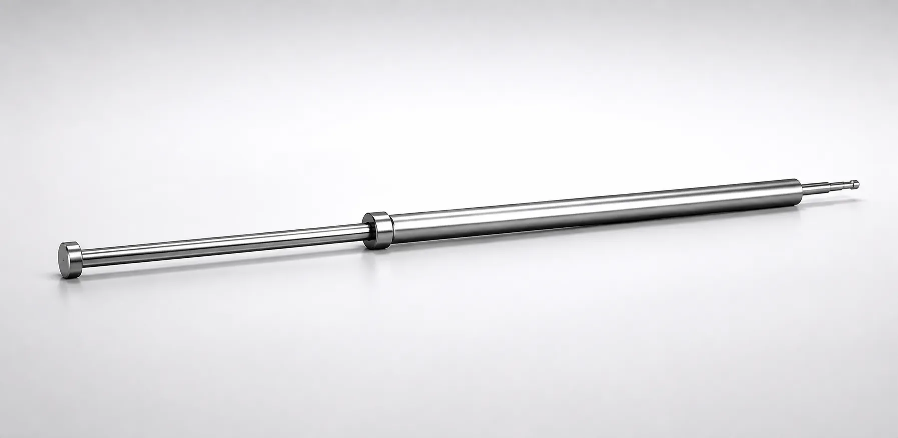
SKH51 Steel Gas Release Straight Ejector Core Pins Flat-Sided
Gas release straight ejector core pins (SKH51 steel) are designed for one-step center pin sets, combining controlled ejection positioning with built-in gas venting. The flat-sided head helps prevent rotation, supporting consistent alignment in production molds.
- Gas release design with a vented structure to improve mold exhaust during operation
- SKH51 steel, quench hardening construction for strong wear resistance
- Supports precision assembly with tight shaft and inner diameter tolerance requirements
- Used in straight ejector arrangements where stable center pin location and repeatable ejection are required
Specifications
66 configurations available
| D/P (Shaft Diameter) (mm) | V (Hole Diameter) (mm) | Center Pin Tip Shape | L (L dimension) (mm) | A (Center pin tip diameter) (mm) | C (Recess diameter) (mm) | E (Center pin tip diameter) (mm) | F (Center pin shaft diameter length) (mm) | Dimension R (mm) | S (V hole diameter length) (mm) | X (Full length of the center pin) (mm) | type |
|---|---|---|---|---|---|---|---|---|---|---|---|
| 4 | 1 ~ 2.5 | A | 50 ~ 120 | - | - | 0.5 ~ 2.49 | 50 ~ 219.5 | - | 1 ~ 7.5 | 70 ~ 220 | - |
| 5 | 1 ~ 3.5 | A | 50 ~ 150 | - | - | 0.5 ~ 3.49 | 50 ~ 249.5 | - | 1 ~ 10.5 | 70 ~ 250 | - |
| 6 | 2 ~ 4.5 | A | 50 ~ 150 | - | - | 0.7 ~ 4.49 | 50 ~ 249.5 | - | 1 ~ 13.5 | 70 ~ 250 | - |
| 7 | 3 ~ 5.5 | A | 50 ~ 150 | - | - | 1 ~ 5.49 | 50 ~ 249.5 | - | 1 ~ 16.5 | 70 ~ 250 | - |
| 8 | 4 ~ 6 | A | 50 ~ 200 | - | - | 1 ~ 5.99 | 50 ~ 249.5 | - | 1 ~ 18 | 70 ~ 250 | - |
| 9 | 5 ~ 7 | A | 50 ~ 200 | - | - | 1.5 ~ 6.99 | 50 ~ 249.5 | - | 1 ~ 21 | 70 ~ 250 | - |
| 10 | 6 ~ 8 | A | 50 ~ 200 | - | - | 2 ~ 7.99 | 50 ~ 249.5 | - | 1 ~ 24 | 70 ~ 250 | - |
| 11 | 7 ~ 9 | A | 50 ~ 200 | - | - | 2 ~ 8.99 | 50 ~ 249.5 | - | 1 ~ 25 | 70 ~ 250 | - |
| 12 | 7 ~ 10 | A | 50 ~ 200 | - | - | 2 ~ 9.99 | 50 ~ 249.5 | - | 1 ~ 25 | 70 ~ 250 | - |
| 13 | 7 ~ 10 | A | 50 ~ 200 | - | - | 2 ~ 9.99 | 50 ~ 249.5 | - | 1 ~ 25 | 70 ~ 250 | - |
| 14 | 7 ~ 12 | A | 50 ~ 200 | - | - | 2 ~ 11.99 | 50 ~ 249.5 | - | 1 ~ 25 | 70 ~ 250 | - |
| 4 | 1 ~ 2.5 | B | 50 ~ 120 | 0.5 ~ 2.49 | - | 0.5 ~ 2.49 | 50 ~ 219.5 | - | 1 ~ 7.5 | 70 ~ 220 | - |
| 5 | 1 ~ 3.5 | B | 50 ~ 150 | 0.5 ~ 3.49 | - | 0.5 ~ 3.49 | 50 ~ 249.5 | - | 1 ~ 10.5 | 70 ~ 250 | - |
| 6 | 2 ~ 4.5 | B | 50 ~ 150 | 0.7 ~ 4.49 | - | 0.7 ~ 4.49 | 50 ~ 249.5 | - | 1 ~ 20 | 70 ~ 250 | - |
| 7 | 3 ~ 5.5 | B | 50 ~ 150 | 1 ~ 5.49 | - | 1 ~ 5.49 | 50 ~ 249.5 | - | 1 ~ 16.5 | 70 ~ 250 | - |
| 8 | 4 ~ 6 | B | 50 ~ 200 | 1 ~ 5.99 | - | 1 ~ 5.99 | 50 ~ 249.5 | - | 1 ~ 18 | 70 ~ 250 | - |
| 9 | 5 ~ 7 | B | 50 ~ 200 | 1.5 ~ 6.99 | - | 1.5 ~ 6.99 | 50 ~ 249.5 | - | 1 ~ 21 | 70 ~ 250 | - |
| 10 | 6 ~ 8 | B | 50 ~ 200 | 2 ~ 7.99 | - | 2 ~ 7.99 | 50 ~ 249.5 | - | 1 ~ 24 | 70 ~ 250 | - |
| 11 | 7 ~ 9 | B | 50 ~ 200 | 2 ~ 8.99 | - | 2 ~ 8.99 | 50 ~ 249.5 | - | 1 ~ 25 | 70 ~ 250 | - |
| 12 | 7 ~ 10 | B | 50 ~ 200 | 2 ~ 9.99 | - | 2 ~ 9.99 | 50 ~ 249.5 | - | 1 ~ 25 | 70 ~ 250 | - |
| 13 | 7 ~ 10 | B | 50 ~ 200 | 2 ~ 9.99 | - | 2 ~ 9.99 | 50 ~ 249.5 | - | 1 ~ 25 | 70 ~ 250 | - |
| 14 | 7 ~ 12 | B | 50 ~ 200 | 2 ~ 11.99 | - | 2 ~ 11.99 | 50 ~ 249.5 | - | 1 ~ 25 | 70 ~ 250 | - |
| 4 | 1 ~ 2.5 | C | 50 ~ 120 | 0.5 ~ 2.49 | - | 0.5 ~ 2.49 | 50 ~ 219.5 | - | 1 ~ 7.5 | 70 ~ 220 | - |
| 5 | 1 ~ 3.5 | C | 50 ~ 150 | 0.5 ~ 3.49 | - | 0.5 ~ 3.49 | 50 ~ 249.5 | - | 1 ~ 10.5 | 70 ~ 250 | - |
| 6 | 2 ~ 4.5 | C | 50 ~ 150 | 0.7 ~ 4.49 | - | 0.7 ~ 4.49 | 50 ~ 249.5 | - | 1 ~ 13.5 | 70 ~ 250 | - |
| 7 | 3 ~ 5.5 | C | 50 ~ 150 | 1 ~ 5.49 | - | 1 ~ 5.49 | 50 ~ 249.5 | - | 1 ~ 16.5 | 70 ~ 250 | - |
| 8 | 4 ~ 6 | C | 50 ~ 200 | 1 ~ 5.99 | - | 1 ~ 5.99 | 50 ~ 249.5 | - | 1 ~ 18 | 70 ~ 250 | - |
| 9 | 5 ~ 7 | C | 50 ~ 200 | 1.5 ~ 6.99 | - | 1.5 ~ 6.99 | 50 ~ 249.5 | - | 1 ~ 21 | 70 ~ 250 | - |
| 10 | 6 ~ 8 | C | 50 ~ 200 | 2 ~ 7.99 | - | 2 ~ 7.99 | 50 ~ 249.5 | - | 1 ~ 24 | 70 ~ 250 | - |
| 11 | 7 ~ 9 | C | 50 ~ 200 | 2 ~ 8.99 | - | 2 ~ 8.99 | 50 ~ 249.5 | - | 1 ~ 25 | 70 ~ 250 | - |
| 12 | 7 ~ 10 | C | 50 ~ 200 | 2 ~ 9.99 | - | 2 ~ 9.99 | 50 ~ 249.5 | - | 1 ~ 25 | 70 ~ 250 | - |
| 13 | 7 ~ 10 | C | 50 ~ 200 | 2 ~ 9.99 | - | 2 ~ 9.99 | 50 ~ 249.5 | - | 1 ~ 25 | 70 ~ 250 | - |
| 14 | 7 ~ 12 | C | 50 ~ 200 | 2 ~ 11.99 | - | 2 ~ 11.99 | 50 ~ 249.5 | - | 1 ~ 25 | 70 ~ 250 | - |
| 4 | 1 ~ 2.5 | D | 50 ~ 120 | 0.5 ~ 2.49 | 0.1 ~ 1 | 0.5 ~ 2.49 | 50 ~ 219.5 | - | 1 ~ 7.5 | 70 ~ 220 | - |
| 5 | 1 ~ 3.5 | D | 50 ~ 150 | 0.5 ~ 3.49 | 0.1 ~ 1 | 0.5 ~ 3.49 | 50 ~ 249.5 | - | 1 ~ 10.5 | 70 ~ 250 | - |
| 6 | 2 ~ 4.5 | D | 50 ~ 150 | 0.7 ~ 4.49 | 0.1 ~ 1.5 | 0.7 ~ 4.49 | 50 ~ 249.5 | - | 1 ~ 13.5 | 70 ~ 250 | - |
| 7 | 3 ~ 5.5 | D | 50 ~ 150 | 1 ~ 5.49 | 0.1 ~ 1 | 1 ~ 5.49 | 50 ~ 249.5 | - | 1 ~ 16.5 | 70 ~ 250 | - |
| 8 | 4 ~ 6 | D | 50 ~ 200 | 1 ~ 5.99 | 0.1 ~ 1 | 1 ~ 5.99 | 50 ~ 249.5 | - | 1 ~ 18 | 70 ~ 250 | - |
| 9 | 5 ~ 7 | D | 50 ~ 200 | 1.5 ~ 6.99 | 0.1 ~ 1 | 1.5 ~ 6.99 | 50 ~ 249.5 | - | 1 ~ 21 | 70 ~ 250 | - |
| 10 | 6 ~ 8 | D | 50 ~ 200 | 2 ~ 7.99 | 0.1 ~ 1 | 2 ~ 7.99 | 50 ~ 249.5 | - | 1 ~ 24 | 70 ~ 250 | - |
| 11 | 7 ~ 9 | D | 50 ~ 200 | 2 ~ 8.99 | 0.1 ~ 1 | 2 ~ 8.99 | 50 ~ 249.5 | - | 1 ~ 25 | 70 ~ 250 | - |
| 12 | 7 ~ 10 | D | 50 ~ 200 | 2 ~ 9.99 | 0.1 ~ 1 | 2 ~ 9.99 | 50 ~ 249.5 | - | 1 ~ 25 | 70 ~ 250 | - |
| 13 | 7 ~ 10 | D | 50 ~ 200 | 2 ~ 9.99 | 0.1 ~ 1 | 2 ~ 9.99 | 50 ~ 249.5 | - | 1 ~ 25 | 70 ~ 250 | - |
| 14 | 7 ~ 12 | D | 50 ~ 200 | 2 ~ 11.99 | 0.1 ~ 1 | 2 ~ 11.99 | 50 ~ 249.5 | - | 1 ~ 25 | 70 ~ 250 | - |
| 4 | 1 ~ 2.5 | E | 50 ~ 120 | 0.5 ~ 2.49 | - | 0.5 ~ 2.49 | 50 ~ 219.5 | 0.3 ~ 0.8 | 1 ~ 7.5 | 70 ~ 220 | - |
| 5 | 1 ~ 3.5 | E | 50 ~ 150 | 0.5 ~ 3.49 | - | 0.5 ~ 3.49 | 50 ~ 249.5 | 0.3 ~ 1.2 | 1 ~ 10.5 | 70 ~ 250 | - |
| 6 | 2 ~ 4.5 | E | 50 ~ 150 | 0.7 ~ 4.49 | - | 0.7 ~ 4.49 | 50 ~ 249.5 | 0.3 ~ 1.4 | 1 ~ 13.5 | 70 ~ 250 | - |
| 7 | 3 ~ 5.5 | E | 50 ~ 150 | 1 ~ 5.49 | - | 1 ~ 5.49 | 50 ~ 249.5 | 0.3 ~ 1.7 | 1 ~ 16.5 | 70 ~ 250 | - |
| 8 | 4 ~ 6 | E | 50 ~ 200 | 1 ~ 5.99 | - | 1 ~ 5.99 | 50 ~ 249.5 | 0.3 ~ 1.9 | 1 ~ 18 | 70 ~ 250 | - |
| 9 | 5 ~ 7 | E | 50 ~ 200 | 1.5 ~ 6.99 | - | 1.5 ~ 6.99 | 50 ~ 249.5 | 0.3 ~ 2.4 | 1 ~ 21 | 70 ~ 250 | - |
Product Guide
Application Scenarios+
These SKH51 gas-release straight ejector core pins are used in injection mold tooling where controlled ejection and improved venting are critical. The straight ejector configuration benefits molds that require stable center pin location during each shot, reducing the risk of positional drift in multi-cavity layouts.
- Automotive connector and housing molds: Flat-sided heads help prevent rotation during assembly and operation, supporting consistent alignment of the ejector core. The internal gas-release design supports better mold exhaust around the core features, which can help limit burn marks and short shots.
- Electronics and thin-wall parts: When gases trapped near the ejector area must be vented, the gas-release structure supports reliable ejection performance across high-cycle production.
- General straight ejector arrangements: The one-step center pin set concept supports accurate mold alignment, making this variant suitable for repeatable ejection positioning with tight shaft/diameter-related tolerances.
Material & Process Details+
SKH51 steel is selected for gas-release ejector core pins because it is engineered for high wear resistance under repeated sliding/impact contact in mold cycles. In common mold steel equivalency terms, SKH51 is comparable to AISI M2.
- Heat treatment: The design is based on quench-hardened construction, targeting a durable working hardness for core-pin service.
- Hardness & performance trade-off: Quench hardening improves wear resistance, which is essential for straight ejector cores exposed to frequent ejection friction and localized stresses. Increased hardness can reduce toughness compared with softer annealed conditions, so proper sizing and alignment are important to avoid chipping under misload.
- Manufacturing process: Produced as straight ejector core pins with controlled shaft and hole geometries, then hardened and finished to meet the specified diameter and recess features.
If alternative steels are used in the same category, higher-toughness grades can reduce chipping risk, while SKH51 emphasizes wear life for long production runs.
Sizing & Selection Guide+
To select the correct dimensions, match the pin shaft and vent hole features to the mold’s core/core-box layout and the ejector alignment requirements. Use the provided ranges for D/P (shaft diameter) and V (hole diameter) to ensure the pin fits the corresponding bore and maintains stable guidance.
- Shaft diameter (D/P): Select from 4–14 mm based on the mold’s drilled or ground guidance and ejector alignment bushings.
- Hole diameter (V): Choose 1–7 mm to correspond with the gas-release/venting feature geometry in your core design.
- Length (L) and full length (X): Use L = 50–120 / 50–150 / 50–200 mm for the center pin dimension you reference in your drawing, and confirm total X = 70–220 / 70–250 mm for clearance to the mold face and ejector stroke envelope.
- Tip/recess geometry: Select center tip shape A/B/C/D/E/S, center tip diameter A/E = 0.5–2 mm, and recess diameter C = 0.1–1 / 0.1–1.5 mm to match mating core recess profiles.
- Tolerance & fit: Flat-sided, one-step center pin sets are intended for stable placement; ensure your guidance bore/inner diameter tolerances are consistent with the pin’s shaft and hole sizes to prevent rotation or misalignment.
Frequently Asked Questions
Which shaft diameter (D/P) range should I specify for SKH51 gas-release straight ejector core pins?+
How do I choose the vent hole diameter (V) for this gas-release ejector pin?+
What length dimensions (L vs. X) do I need to verify against my mold drawing?+
How does the flat-sided head affect installation and alignment?+
What tip shapes and micro-dimensions (A/E/C) are available for matching to my core feature?+
Related Products
Need Custom Specifications?
Our engineering team can help with custom configurations, material selection, and volume pricing.