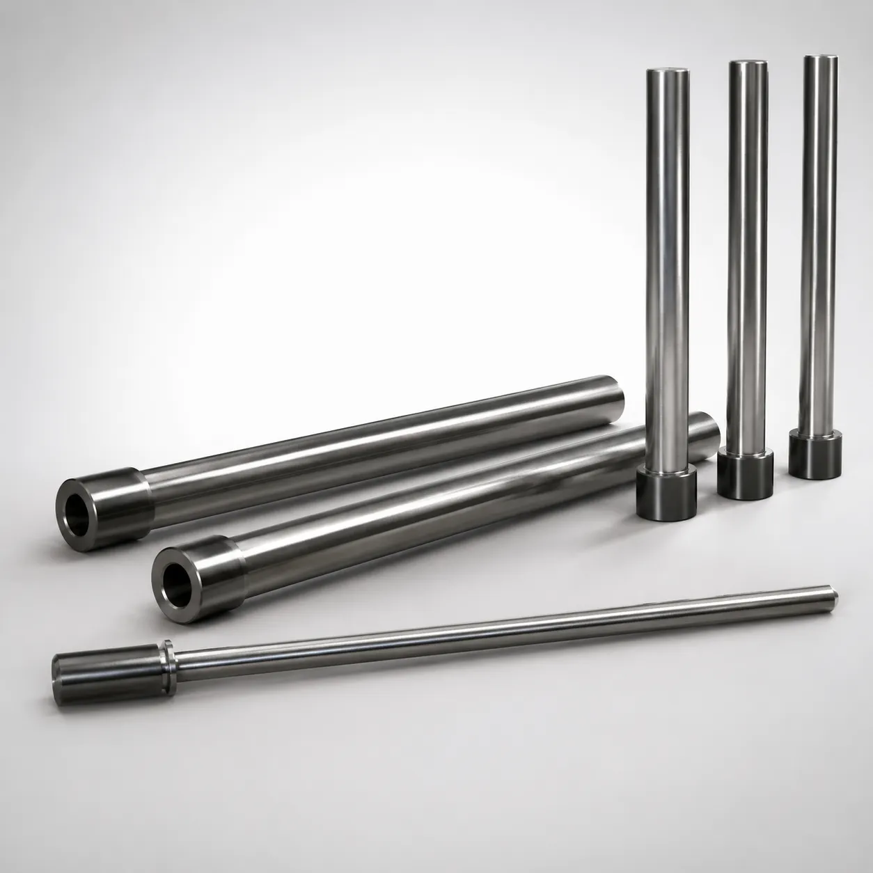
SKD61 Steel Straight Ejector Sleeves & One-Step Center Pin Sets
Straight Ejector Sleeves & One-Step Center Pin Sets (SKD61 steel) provide a compact, one-step centering arrangement for stable ejection. The nitrided surface treatment improves wear resistance in repetitive mold cycles.
- Center pin set composition designed for consistent H7 centering fit
- Nitrided surface boosts durability and helps maintain dimensional stability
- Controlled shaft diameter with tight negative tolerance reference -0.01/-0.02 for reliable alignment
- Suitable for straight ejection systems in tooling and high-cycle production molds
Specifications
142 configurations available
| Head Thickness | D/P (Shaft Diameter) (mm) | V (Hole Diameter) (mm) | Center Pin Tip Shape | L (L dimension) (mm) | A (Center pin tip diameter) (mm) | C (Recess diameter) (mm) | E (Center pin tip diameter) (mm) | F (Center pin shaft diameter length) (mm) | Dimension R (mm) | X (Full length of the center pin) (mm) | type |
|---|---|---|---|---|---|---|---|---|---|---|---|
| 6mm(JIS) | 4 | 1.5 ~ 2.5 | A | 80 ~ 200 | - | - | 0.7 ~ 2.49 | 50 ~ 299.5 | - | 100 ~ 300 | - |
| 6mm(JIS) | 4.5 | 1.5 ~ 2.5 | A | 80 ~ 200 | - | - | 1 ~ 2.49 | 50 ~ 299.5 | - | 100 ~ 300 | - |
| 6mm(JIS) | 5 | 2 ~ 3 | A | 80 ~ 275 | - | - | 1 ~ 2.99 | 50 ~ 374.5 | - | 100 ~ 375 | - |
| 6mm(JIS) | 5.5 | 2 ~ 3 | A | 80 ~ 275 | - | - | 1 ~ 2.99 | 50 ~ 374.5 | - | 100 ~ 375 | - |
| 6mm(JIS) | 6 | 2 ~ 4 | A | 80 ~ 400 | - | - | 1 ~ 3.99 | 50 ~ 499.5 | - | 100 ~ 500 | - |
| 6mm(JIS) | 6.5 | 2 ~ 4 | A | 80 ~ 400 | - | - | 1 ~ 3.99 | 50 ~ 499.5 | - | 100 ~ 500 | - |
| 6mm(JIS) | 7 | 2 ~ 4.5 | A | 80 ~ 400 | - | - | 1 ~ 4.49 | 50 ~ 499.5 | - | 100 ~ 500 | - |
| 6mm(JIS) | 7.5 | 3 ~ 4.5 | A | 80 ~ 325 | - | - | 1.5 ~ 4.49 | 50 ~ 424.5 | - | 100 ~ 425 | - |
| 8mm(JIS) | 8 | 2 ~ 5 | A | 80 ~ 400 | - | - | 2 ~ 4.99 | 50 ~ 499.5 | - | 100 ~ 500 | - |
| 8mm(JIS) | 8 | 3 ~ 5 | A | 80 ~ 400 | - | - | 2 ~ 4.99 | 50 ~ 499.5 | - | 100 ~ 500 | - |
| 8mm(JIS) | 10 | 4 ~ 6.5 | A | 80 ~ 400 | - | - | 2 ~ 6.49 | 50 ~ 499.5 | - | 100 ~ 500 | - |
| 8mm(JIS) | 12 | 4 ~ 8.5 | A | 80 ~ 400 | - | - | 2 ~ 8.49 | 50 ~ 499.5 | - | 100 ~ 500 | - |
| 6mm(JIS) | 4 | 1.5 ~ 2.5 | B | 80 ~ 200 | 0.7 ~ 2.49 | - | 0.7 ~ 2.49 | 50 ~ 299.5 | - | 100 ~ 300 | - |
| 6mm(JIS) | 4.5 | 1.5 ~ 2.5 | B | 80 ~ 200 | 1 ~ 2.49 | - | 1 ~ 2.49 | 50 ~ 299.5 | - | 100 ~ 300 | - |
| 6mm(JIS) | 5 | 2 ~ 3 | B | 80 ~ 275 | 1 ~ 2.99 | - | 1 ~ 2.99 | 50 ~ 374.5 | - | 100 ~ 375 | - |
| 6mm(JIS) | 5.5 | 2 ~ 3 | B | 80 ~ 275 | 1 ~ 2.99 | - | 1 ~ 2.99 | 50 ~ 374.5 | - | 100 ~ 375 | - |
| 6mm(JIS) | 6 | 2 ~ 4 | B | 80 ~ 400 | 1 ~ 3.99 | - | 1 ~ 3.99 | 50 ~ 499.5 | - | 100 ~ 500 | - |
| 6mm(JIS) | 6.5 | 2 ~ 4 | B | 80 ~ 400 | 1 ~ 3.99 | - | 1 ~ 3.99 | 50 ~ 499.5 | - | 100 ~ 500 | - |
| 6mm(JIS) | 7 | 2 ~ 4.5 | B | 80 ~ 400 | 1 ~ 4.49 | - | 1 ~ 4.49 | 50 ~ 499.5 | - | 100 ~ 500 | - |
| 6mm(JIS) | 7.5 | 3 ~ 4.5 | B | 80 ~ 325 | 1.5 ~ 4.49 | - | 1.5 ~ 4.49 | 50 ~ 424.5 | - | 100 ~ 425 | - |
| 8mm(JIS) | 8 | 2 ~ 5 | B | 80 ~ 400 | 2 ~ 4.99 | - | 2 ~ 4.99 | 50 ~ 499.5 | - | 100 ~ 500 | - |
| 8mm(JIS) | 8 | 3 ~ 5 | B | 80 ~ 400 | 2 ~ 4.99 | - | 2 ~ 4.99 | 50 ~ 499.5 | - | 100 ~ 500 | - |
| 8mm(JIS) | 10 | 4 ~ 6.5 | B | 80 ~ 400 | 2 ~ 6.49 | - | 2 ~ 6.49 | 50 ~ 499.5 | - | 100 ~ 500 | - |
| 8mm(JIS) | 12 | 4 ~ 8.5 | B | 80 ~ 400 | 2 ~ 8.49 | - | 2 ~ 8.49 | 50 ~ 499.5 | - | 100 ~ 500 | - |
| 6mm(JIS) | 4 | 1.5 ~ 2.5 | C | 80 ~ 200 | 0.7 ~ 2.49 | - | 0.7 ~ 2.49 | 50 ~ 299 | - | 100 ~ 300 | - |
| 6mm(JIS) | 4.5 | 1.5 ~ 2.5 | C | 80 ~ 200 | 1 ~ 2.49 | - | 1 ~ 2.49 | 50 ~ 299.5 | - | 100 ~ 300 | - |
| 6mm(JIS) | 5 | 2 ~ 3 | C | 80 ~ 275 | 1 ~ 2.99 | - | 1 ~ 2.99 | 50 ~ 374 | - | 100 ~ 375 | - |
| 6mm(JIS) | 5.5 | 2 ~ 3 | C | 80 ~ 275 | 1 ~ 2.99 | - | 1 ~ 2.99 | 50 ~ 374 | - | 100 ~ 375 | - |
| 6mm(JIS) | 6 | 2 ~ 4 | C | 80 ~ 400 | 1 ~ 3.99 | - | 1 ~ 3.99 | 50 ~ 499 | - | 100 ~ 500 | - |
| 6mm(JIS) | 6.5 | 2 ~ 4 | C | 80 ~ 400 | 1 ~ 3.99 | - | 1 ~ 3.99 | 50 ~ 499 | - | 100 ~ 500 | - |
| 6mm(JIS) | 7 | 2 ~ 4.5 | C | 80 ~ 400 | 1 ~ 4.49 | - | 1 ~ 4.49 | 50 ~ 499 | - | 100 ~ 500 | - |
| 6mm(JIS) | 7.5 | 3 ~ 4.5 | C | 80 ~ 325 | 1.5 ~ 4.49 | - | 1.5 ~ 4.49 | 50 ~ 424 | - | 100 ~ 425 | - |
| 8mm(JIS) | 8 | 2 ~ 5 | C | 80 ~ 400 | 2 ~ 4.99 | - | 2 ~ 4.99 | 50 ~ 499 | - | 100 ~ 500 | - |
| 8mm(JIS) | 8 | 3 ~ 5 | C | 80 ~ 400 | 2 ~ 4.99 | - | 2 ~ 4.99 | 50 ~ 499 | - | 100 ~ 500 | - |
| 8mm(JIS) | 10 | 4 ~ 6.5 | C | 80 ~ 400 | 2 ~ 6.49 | - | 2 ~ 6.49 | 50 ~ 499 | - | 100 ~ 500 | - |
| 8mm(JIS) | 12 | 4 ~ 8.5 | C | 80 ~ 400 | 2 ~ 8.49 | - | 2 ~ 8.49 | 50 ~ 499 | - | 100 ~ 500 | - |
| 6mm(JIS) | 4 | 1.5 ~ 2.5 | D | 80 ~ 200 | 0.7 ~ 2.49 | 0.1 ~ 1 | 0.7 ~ 2.49 | 50 ~ 299 | - | 100 ~ 300 | - |
| 6mm(JIS) | 4.5 | 1.5 ~ 2.5 | D | 80 ~ 200 | 1 ~ 2.49 | 0.1 ~ 0.7 | 1 ~ 2.49 | 50 ~ 299.5 | - | 100 ~ 300 | - |
| 6mm(JIS) | 5 | 2 ~ 3 | D | 80 ~ 275 | 1 ~ 2.99 | 0.1 ~ 1 | 1 ~ 2.99 | 50 ~ 374 | - | 100 ~ 375 | - |
| 6mm(JIS) | 5.5 | 2 ~ 3 | D | 80 ~ 275 | 1 ~ 2.99 | 0.1 ~ 1 | 1 ~ 2.99 | 50 ~ 374 | - | 100 ~ 375 | - |
| 6mm(JIS) | 6 | 2 ~ 4 | D | 80 ~ 400 | 1 ~ 3.99 | 0.1 ~ 1 | 1 ~ 3.99 | 50 ~ 499 | - | 100 ~ 500 | - |
| 6mm(JIS) | 6.5 | 2 ~ 4 | D | 80 ~ 400 | 1 ~ 3.99 | 0.1 ~ 1 | 1 ~ 3.99 | 50 ~ 499 | - | 100 ~ 500 | - |
| 6mm(JIS) | 7 | 2 ~ 4.5 | D | 80 ~ 400 | 1 ~ 4.49 | 0.1 ~ 1 | 1 ~ 4.49 | 50 ~ 499 | - | 100 ~ 500 | - |
| 6mm(JIS) | 7.5 | 3 ~ 4.5 | D | 80 ~ 325 | 1.5 ~ 4.49 | 0.1 ~ 1 | 1.5 ~ 4.49 | 50 ~ 424 | - | 100 ~ 425 | - |
| 8mm(JIS) | 8 | 2 ~ 5 | D | 80 ~ 400 | 2 ~ 4.99 | 0.1 ~ 1 | 2 ~ 4.99 | 50 ~ 499 | - | 100 ~ 500 | - |
| 8mm(JIS) | 8 | 3 ~ 5 | D | 80 ~ 400 | 2 ~ 4.99 | 0.1 ~ 1 | 2 ~ 4.99 | 50 ~ 499 | - | 100 ~ 500 | - |
| 8mm(JIS) | 10 | 4 ~ 6.5 | D | 80 ~ 400 | 2 ~ 6.49 | 0.1 ~ 1 | 2 ~ 6.49 | 50 ~ 499 | - | 100 ~ 500 | - |
| 8mm(JIS) | 12 | 4 ~ 8.5 | D | 80 ~ 400 | 2 ~ 8.49 | 0.1 ~ 1 | 2 ~ 8.49 | 50 ~ 499 | - | 100 ~ 500 | - |
| 6mm(JIS) | 4 | 1.5 ~ 2.5 | E | 80 ~ 200 | 0.7 ~ 2.49 | - | 0.7 ~ 2.49 | 50 ~ 299 | 0.3 ~ 0.8 | 100 ~ 300 | - |
| 6mm(JIS) | 4.5 | 2 ~ 2.5 | E | 80 ~ 200 | 1 ~ 2.49 | 0.1 ~ 0.7 | 1 ~ 2.49 | 50 ~ 299.5 | - | 100 ~ 300 | - |
Product Guide
Application Scenarios+
This SKD61-based straight ejector sleeve and one-step center pin set is designed for injection mold tooling where compact, repeatable alignment is critical during ejection and withdrawal. The one-step centering helps maintain straight-motion of ejector components, reducing the risk of scuffing or uneven wear under high cycle counts.
- Automotive connector and terminal housings: Use when you need stable, straight ejection in thin-to-medium wall parts; the nitrided wear surface supports durability across repetitive mold cycles while the optimized H7 centering fit promotes consistent positioning.
- Appliance and industrial casing molds: Suitable for longer ejection strokes where alignment repeatability affects cycle stability; the controlled shaft diameter range supports reliable mating with mating guide features.
- Electronics enclosure tooling: The compact one-step layout is well-suited to crowded mold stacks, helping keep ejection aligned without increasing overall tool height.
Configured with the specified diameter and length ranges, this variant is particularly effective where wear resistance and dimensional stability must be maintained at production tempo.
Material & Process Details+
The component uses SKD61 steel, a hot-work die steel commonly aligned with H13 in many international references. SKD61 is chosen for its balance of hardness, toughness, and resistance to wear during repeated sliding in mold operation.
- Surface treatment: A nitrided surface treatment is specified to improve wear resistance and help maintain dimensional stability under repetitive ejection motion.
- Hardness and trade-offs: Typical nitriding results in a hard, wear-resistant surface layer while the steel core retains toughness; this helps reduce chipping risk compared with fully through-hardened, very brittle conditions.
Compared with alternatives lacking nitriding, the nitrided SKD61 variant better resists surface degradation from friction and micro-abrasion during high-cycle molding.
Note: Specific HRC values are not provided in the input data.
Sizing & Selection Guide+
To select the correct ejector sleeve and center pin set dimensions, start by matching the D/P (shaft diameter) to your mating guide hole and centering feature. The product is optimized for an H7 centering fit, so ensure your core/cavity and guide partner dimensions are designed to achieve the intended fit class.
- Shaft diameter: choose D/P = 4 ~ 12 mm based on the required centering pin size for the mold.
- Hole diameter: confirm V = 1.5 ~ 4 mm for the center pin hole interface.
- Length selections: match L and X to your mold stack-up and ejection geometry (e.g., L: 80–200, 80–275, 80–400, 80–325; X: 100–300, 100–375, 100–500, 100–425).
Use the provided negative tolerance reference -0.01 / -0.02 for shaft alignment planning. Confirm pin tip constraints by selecting the applicable tip shape (A, B, C, D, E, S) and corresponding tip diameter range 0.7 ~ 2 mm so clearances and recess features (e.g., C = 0.1–1 or 0.1–0.7 mm) meet your ejection alignment requirements.
Frequently Asked Questions
How does the H7 centering fit requirement affect the mating mold guide design for these straight ejector sleeves and center pins?+
What benefits does the nitrided surface treatment provide for high-cycle straight ejection applications?+
Which dimension should I prioritize when selecting a set for my mold: D/P, L, or X?+
Can I choose different center pin tip shapes (A, B, C, D, E, S) and still rely on stable alignment?+
What ranges are available for shaft diameter and hole diameter, and how do they relate to compatibility?+
Related Products
Need Custom Specifications?
Our engineering team can help with custom configurations, material selection, and volume pricing.