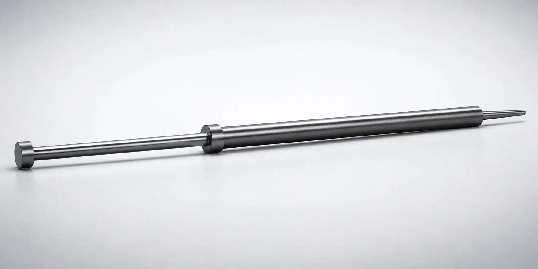
SKD61 Steel Straight Ejector Sleeves & One-Step Center Pin Sets
SKD61 straight ejector sleeves & one-step center pin sets are designed to support stable centering and controlled ejection in die assemblies. The nitrided surface treatment helps resist wear while maintaining consistent fit at the interface.
- One-step center pin set configuration for reliable positional control during ejector cycles
- Nitrided SKD61 steel construction improves abrasion resistance under repeated operation
- Controlled fit using H7 inner diameter tolerance for repeatable alignment
- Suitable for injection molds and stamping dies requiring precise sleeve-pin engagement
Specifications
137 configurations available
| Head Thickness | D/P (Shaft Diameter) (mm) | V (Hole Diameter) (mm) | Center Pin Tip Shape | L (L dimension) (mm) | A (Center pin tip diameter) (mm) | C (Recess diameter) (mm) | E (Center pin tip diameter) (mm) | F (Center pin shaft diameter length) (mm) | Dimension R (mm) | S (V hole diameter length) (mm) | X (Full length of the center pin) (mm) | type |
|---|---|---|---|---|---|---|---|---|---|---|---|---|
| 6mm(JIS) | 4 | 2 ~ 2.5 | A | 50 ~ 200 | - | - | 0.7 ~ 2.49 | 50 ~ 299.5 | - | 30 ~ 100 | 70 ~ 300 | - |
| 6mm(JIS) | 4.5 | 2 ~ 2.5 | A | 50 ~ 200 | 0.7 ~ 2.49 | - | 2.5 | 50 ~ 299.5 | - | 20 ~ 100 | 70 ~ 300 | - |
| 6mm(JIS) | 4.5 | 2 ~ 2.5 | A | 50 ~ 200 | 0.7 ~ 2.49 | - | 0.7 ~ 2.49 | 50 ~ 299.5 | - | 20 ~ 100 | 70 ~ 300 | - |
| 6mm(JIS) | 5 | 2 ~ 3 | A | 50 ~ 250 | - | - | 1 ~ 2.99 | 50 ~ 349.5 | - | 20 ~ 100 | 70 ~ 350 | - |
| 6mm(JIS) | 5.5 | 2 ~ 3.5 | A | 50 ~ 250 | - | - | 1 ~ 3.49 | 50 ~ 349.5 | - | 20 ~ 100 | 70 ~ 350 | - |
| 6mm(JIS) | 6 | 2 ~ 4 | A | 80 ~ 300 | - | - | 1 ~ 3.99 | 100 ~ 399.5 | - | 30 ~ 100 | 70 ~ 400 | - |
| 6mm(JIS) | 6.5 | 2.5 ~ 4 | A | 80 ~ 300 | - | - | 1 ~ 3.99 | 50 ~ 399.5 | - | 20 ~ 100 | 100 ~ 400 | - |
| 6mm(JIS) | 7 | 2.5 ~ 4.5 | A | 80 ~ 300 | - | - | 1.5 ~ 4.49 | 50 ~ 399.5 | - | 30 ~ 100 | 100 ~ 400 | - |
| 6mm(JIS) | 7.5 | 2.5 ~ 4.5 | A | 80 ~ 300 | - | - | 1.5 ~ 4.49 | 50 ~ 399.5 | - | 20 ~ 40 | 100 ~ 400 | - |
| 8mm(JIS) | 8 | 2.5 ~ 5.5 | A | 80 ~ 300 | - | - | 2 ~ 5.49 | 50 ~ 399.5 | - | 30 ~ 100 | 100 ~ 400 | - |
| 8mm(JIS) | 10 | 4 ~ 7 | A | 80 ~ 300 | - | - | 2 ~ 6.99 | 50 ~ 399.5 | - | 30 ~ 40 | 100 ~ 400 | - |
| 8mm(JIS) | 10 | 4 ~ 7 | A | 80 ~ 300 | - | - | 2 ~ 6.99 | 50 ~ 399.5 | - | 31 ~ 100 | 100 ~ 400 | - |
| 8mm(JIS) | 12 | 4 ~ 8 | A | 80 ~ 300 | - | - | 2 ~ 7.99 | 50 ~ 399.5 | - | 20 ~ 100 | 100 ~ 400 | - |
| 6mm(JIS) | 4 | 2 ~ 2.5 | B | 50 ~ 200 | 0.7 ~ 2.49 | - | 0.7 ~ 2.49 | 50 ~ 299.5 | - | 20 ~ 100 | 70 ~ 300 | - |
| 6mm(JIS) | 4.5 | 2 ~ 2.5 | B | 50 ~ 200 | 0.7 ~ 2.49 | - | 0.7 ~ 2.49 | 50 ~ 299.5 | - | 20 ~ 100 | 70 ~ 300 | - |
| 6mm(JIS) | 5 | 2 ~ 3 | B | 50 ~ 250 | 1 ~ 2.99 | - | 1 ~ 2.99 | 50 ~ 349.5 | - | 20 ~ 100 | 70 ~ 350 | - |
| 6mm(JIS) | 5.5 | 2 ~ 3.5 | B | 50 ~ 250 | 1 ~ 3.49 | - | 1 ~ 3.49 | 50 ~ 349.5 | - | 20 ~ 100 | 70 ~ 350 | - |
| 6mm(JIS) | 6 | 2.5 ~ 4 | B | 80 ~ 300 | 1 ~ 3.99 | - | 1 ~ 3.99 | 50 ~ 399.5 | - | 20 ~ 100 | 100 ~ 400 | - |
| 6mm(JIS) | 6.5 | 2.5 ~ 4 | B | 80 ~ 300 | 1 ~ 3.99 | - | 1 ~ 3.99 | 50 ~ 399.5 | - | 30 ~ 100 | 100 ~ 400 | - |
| 6mm(JIS) | 7 | 2.5 ~ 4.5 | B | 80 ~ 300 | 1.5 ~ 4.49 | - | 1.5 ~ 4.49 | 50 ~ 399.5 | - | 20 ~ 100 | 100 ~ 400 | - |
| 6mm(JIS) | 7.5 | 2.5 ~ 4.5 | B | 80 ~ 300 | 1.5 ~ 4.49 | - | 1.5 ~ 4.49 | 50 ~ 399.5 | - | 20 ~ 100 | 100 ~ 400 | - |
| 8mm(JIS) | 8 | 2.5 ~ 5.5 | B | 80 ~ 300 | 2 ~ 5.49 | - | 2 ~ 5.49 | 50 ~ 399.5 | - | 20 ~ 100 | 100 ~ 400 | - |
| 8mm(JIS) | 10 | 4 ~ 7 | B | 80 ~ 300 | 2 ~ 6.99 | - | 2 ~ 6.99 | 50 ~ 399.5 | - | 30 ~ 100 | 100 ~ 400 | - |
| 8mm(JIS) | 12 | 4 ~ 8 | B | 80 ~ 300 | 2 ~ 7.99 | - | 2 ~ 7.99 | 50 ~ 399.5 | - | 20 ~ 100 | 100 ~ 400 | - |
| 6mm(JIS) | 4 | 2 ~ 2.5 | C | 50 ~ 200 | 0.1 ~ 2.49 | - | 0.1 ~ 2.49 | 50 ~ 299.5 | - | 20 ~ 100 | 70 ~ 300 | - |
| 6mm(JIS) | 4.5 | 2 ~ 2.5 | C | 50 ~ 200 | 0.7 ~ 2.49 | - | 0.7 ~ 2.49 | 50 ~ 299.5 | - | 20 ~ 100 | 70 ~ 300 | - |
| 6mm(JIS) | 5 | 2 ~ 3 | C | 50 ~ 250 | 1 ~ 2.99 | - | 1 ~ 2.99 | 50 ~ 349.5 | - | 20 ~ 100 | 70 ~ 350 | - |
| 6mm(JIS) | 5.5 | 2 ~ 3.5 | C | 50 ~ 250 | 1 ~ 3.49 | - | 1 ~ 3.49 | 50 ~ 349.5 | - | 30 ~ 100 | 70 ~ 350 | - |
| 6mm(JIS) | 6 | 2.5 ~ 4 | C | 80 ~ 300 | 1 ~ 3.99 | - | 1 ~ 3.99 | 100 ~ 399.5 | - | 20 ~ 100 | 70 ~ 400 | - |
| 6mm(JIS) | 6.5 | 2.5 ~ 4 | C | 80 ~ 300 | 1 ~ 3.99 | - | 1 ~ 3.99 | 50 ~ 399.5 | - | 20 ~ 100 | 100 ~ 400 | - |
| 6mm(JIS) | 7 | 2.5 ~ 4.5 | C | 80 ~ 300 | 1.5 ~ 4.49 | - | 1.5 ~ 4.49 | 50 ~ 399.5 | - | 20 ~ 100 | 100 ~ 400 | - |
| 6mm(JIS) | 7.5 | 2.5 ~ 4.5 | C | 80 ~ 300 | 1.5 ~ 4.49 | - | 1.5 ~ 2.4 | 50 ~ 399.5 | - | 30 ~ 100 | 100 ~ 400 | - |
| 6mm(JIS) | 7.5 | 2.5 ~ 4.5 | C | 80 ~ 300 | 1.5 ~ 4.49 | - | 1.5 ~ 4.49 | 50 ~ 399.5 | - | 30 ~ 100 | 100 ~ 400 | - |
| 8mm(JIS) | 8 | 2.5 ~ 5.5 | C | 80 ~ 300 | 2 ~ 5.49 | - | 2 ~ 5.49 | 50 ~ 399.5 | - | 20 ~ 100 | 100 ~ 400 | - |
| 8mm(JIS) | 10 | 4 ~ 7 | C | 80 ~ 300 | 2 ~ 6.99 | - | 2 ~ 6.99 | 50 ~ 399.5 | - | 20 ~ 100 | 100 ~ 400 | - |
| 8mm(JIS) | 12 | 4 ~ 8 | C | 80 ~ 300 | 2 ~ 7.99 | - | 2 ~ 7.99 | 50 ~ 399.5 | - | 20 ~ 100 | 100 ~ 400 | - |
| 6mm(JIS) | 4 | 2 ~ 2.5 | D | 50 ~ 200 | 0.7 ~ 2.49 | 0.1 ~ 1 | 0.7 ~ 2.49 | 50 ~ 299.5 | - | 20 ~ 100 | 70 ~ 300 | - |
| 6mm(JIS) | 4.5 | 2 ~ 2.5 | D | 50 ~ 200 | 0.7 ~ 2.49 | 0.1 ~ 1 | 0.7 ~ 2.49 | 50 ~ 299.5 | - | 20 ~ 100 | 70 ~ 300 | - |
| 6mm(JIS) | 5 | 2 ~ 3 | D | 50 ~ 250 | 1 ~ 2.99 | 0.1 ~ 1 | 1 ~ 2.99 | 50 ~ 349.5 | - | 20 ~ 100 | 70 ~ 350 | - |
| 6mm(JIS) | 5.5 | 2 ~ 3.5 | D | 50 ~ 250 | 1 ~ 3.49 | 0.1 ~ 1 | 1 ~ 3.49 | 50 ~ 349.5 | - | 20 ~ 100 | 70 ~ 350 | - |
| 6mm(JIS) | 6 | 2.5 ~ 4 | D | 80 ~ 300 | 1 ~ 3.99 | 0.1 ~ 1 | 1 ~ 3.99 | 100 ~ 399.5 | - | 30 ~ 100 | 70 ~ 400 | - |
| 6mm(JIS) | 6.5 | 2.5 ~ 4 | D | 80 ~ 300 | 1 ~ 3.99 | 0.1 ~ 1 | 1 ~ 3.99 | 50 ~ 399.5 | - | 20 ~ 100 | 100 ~ 400 | - |
| 6mm(JIS) | 7 | 2.5 ~ 4.5 | D | 80 ~ 300 | 1.5 ~ 4.49 | 0.1 ~ 1 | 1.5 ~ 4.49 | 50 ~ 399.5 | - | 20 ~ 40 | 100 ~ 400 | - |
| 6mm(JIS) | 7.5 | 2.5 ~ 4.5 | D | 80 ~ 300 | 1.5 ~ 4.49 | 0.1 ~ 1 | 1.5 ~ 4.49 | 50 ~ 399.5 | - | 30 ~ 40 | 100 ~ 400 | - |
| 8mm(JIS) | 8 | 2.5 ~ 5.5 | D | 80 ~ 300 | 2 ~ 5.49 | 0.1 ~ 1 | 2 ~ 5.49 | 50 ~ 399.5 | - | 20 ~ 100 | 100 ~ 400 | - |
| 8mm(JIS) | 10 | 4 ~ 7 | D | 80 ~ 300 | 2 ~ 6.99 | 0.1 ~ 1 | 2 ~ 6.99 | 50 ~ 399.5 | - | 30 ~ 100 | 100 ~ 400 | - |
| 8mm(JIS) | 12 | 4 ~ 8 | D | 80 ~ 300 | 2 ~ 7.99 | 0.1 ~ 1 | 2 ~ 7.99 | 50 ~ 399.5 | - | 20 ~ 100 | 100 ~ 400 | - |
| 6mm(JIS) | 4 | 2 ~ 2.5 | E | 50 ~ 200 | 0.7 ~ 2.49 | - | 0.7 ~ 2.49 | 50 ~ 299.5 | 0.3 ~ 5 | 20 ~ 100 | 70 ~ 300 | - |
| 6mm(JIS) | 4.5 | 2 ~ 2.5 | E | 50 ~ 200 | 0.7 ~ 2.49 | - | 0.7 ~ 2.49 | 50 ~ 299.5 | 0.3 ~ 5 | 20 ~ 100 | 70 ~ 300 | - |
| 6mm(JIS) | 5 | 2 ~ 3 | E | 50 ~ 250 | 1 ~ 2.99 | - | 1 ~ 2.99 | 50 ~ 349.5 | 0.3 ~ 5 | 20 ~ 100 | 70 ~ 350 | - |
Product Guide
Application Scenarios+
This nitrided SKD61 ejector sleeve and one-step center pin set is used to maintain stable centering and repeatable ejection in injection mold tooling where the sleeve-pin interface directly affects part quality.
- Automotive and appliance connector molds: The one-step center pin set configuration helps control positional accuracy over repeated ejector cycles, while the nitrided surface supports wear resistance in the sleeve engagement area.
- Medical device housings and precision components: The controlled interface fit, specified as H7 for alignment, reduces variation in tip-to-hole engagement, supporting consistent ejection without introducing misalignment marks.
- Electronics and thin-wall parts (core cavity alignment): Straight ejector sleeves combined with center pin tip shapes (A, B, C, D, E, S) allow designers to tune engagement geometry for reliable ejection under steady production loads.
Choose this variant when you need both abrasion resistance from nitriding and dimensional control at the sleeve-pin interface.
Material & Process Details+
SKD61 (tool steel, commonly referenced as an H13-equivalent grade in industry) is selected for ejector components because it balances toughness with hot-work and wear resistance. The nitrided surface treatment enhances surface hardness and abrasion resistance at the sleeve-pin sliding interface, helping maintain fit through repeated ejector cycles.
- Heat treatment / state: nitrided surface on SKD61; internally the component remains SKD61 in its hardened tool-steel condition as produced for die wear parts.
- Hardness & trade-offs: nitriding improves wear resistance at the surface, while the core toughness supports shock resistance during ejector actuation.
- Fit and function: with an H7 interface tolerance, wear control is critical to preserve alignment accuracy.
Compared with non-nitrided tool steels, the nitrided SKD61 option typically prioritizes longevity and dimensional stability at the contact zone, at the expense of requiring proper handling to avoid surface damage.
Sizing & Selection Guide+
Select the correct sleeve and center pin dimensions by matching the engagement interface and overall stack-up to your mold cavity/core layout. This series provides variable ranges for D/P (shaft diameter) = 4 ~ 12 mm and V (hole diameter) = 2 ~ 4 mm, which must correspond to the designed sleeve and receiver hole geometry.
- Center pin length: choose X (full length) from 70 ~ 300, 70 ~ 350, 70 ~ 400, or 100 ~ 400 mm based on your die thickness and required protrusion during ejection.
- Hole depth / V-hole length: select S from the available ranges (e.g., 30 ~ 100, 20 ~ 100, 20 ~ 40, 30 ~ 40, 31 ~ 100) to ensure proper tip engagement without bottoming.
- Tip geometry: pick the center pin tip shape (A, B, C, D, E, S) and match tip diameter options (e.g., A = 0.1 ~ 2 mm or E = 0.1 ~ 2.5 mm) to the recess constraints.
For alignment, this series uses a H7 fit inner diameter tolerance; maintain nominal diameter mapping to preserve the intended clearance/fit at the sleeve-pin interface.
Frequently Asked Questions
Which dimensions are critical to preserve the H7 sleeve-pin alignment in SKD61 ejector sleeve sets?+
How do I choose the correct center pin length range (X) for my mold die thickness and ejection stroke?+
What are the typical constraints for V-hole diameter and V-hole length (V and S) in this one-step center pin configuration?+
How should I select the center pin tip diameter (A or E) and recess diameter (C) for stable sleeve-pin engagement?+
Is nitriding on SKD61 necessary for this sleeve-pin system, and what benefit does it provide under repeated ejector cycles?+
Related Products
Need Custom Specifications?
Our engineering team can help with custom configurations, material selection, and volume pricing.