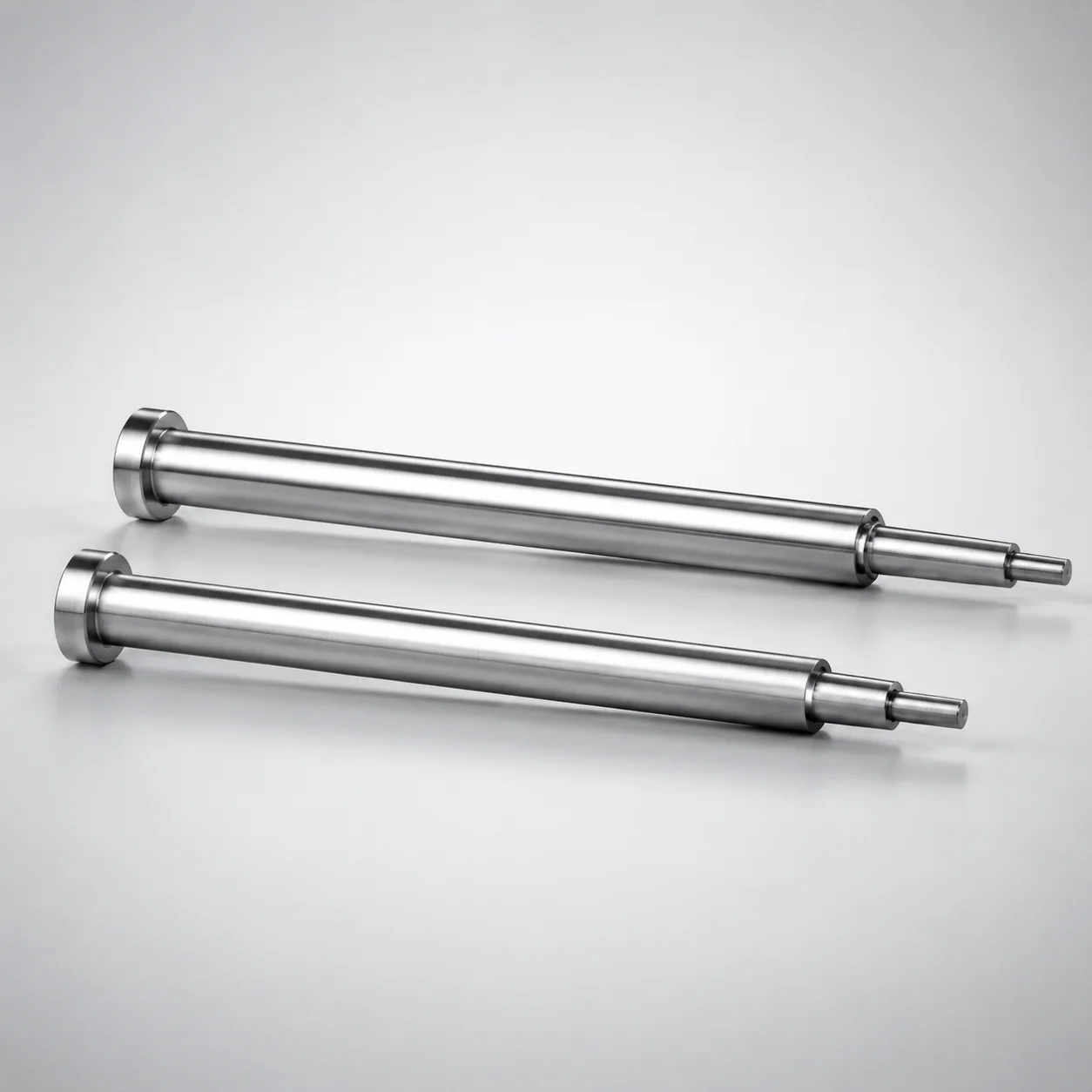
M2 Steel Two-Step Center Pins
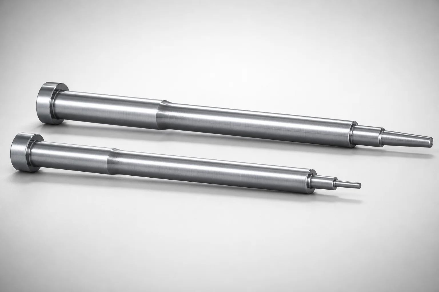
Two-step center pins (M2 steel) are engineered for accurate mold alignment using a two-step profile that supports repeatable locating. The SKH51 construction helps maintain dimensional stability under production load.
- Two-step geometry improves seating stability and alignment repeatability
- Built from SKH51 hardened steel for reliable wear resistance
- Tip geometry supports tight ±0.01 tolerance for consistent locating
- Used for center locating in die and mold assemblies
Specifications
840 configurations available
| Shaft Diameter Tolerance | D/P (Shaft Diameter) (mm) | Step Shape | Compatible Sleeve Hole Diameter Tolerance | Type of the second step | A (Tip part) (mm) | C (Tip part) (mm) | E (Tip diameter in the tip part) (mm) | F (Shaft diameter length) (mm) | G (Tip C chamfering width on the tip part) (mm) | J (Tip part) (mm) | L (L dimension) (mm) | Q (Tip R chamfering on the tip part) (mm) | R (Tip part) (mm) | V (Tip diameter in the tip part) (mm) | Dimension Y (mm) | type |
|---|---|---|---|---|---|---|---|---|---|---|---|---|---|---|---|---|
| 0/-0.005 | 1 | A | +0.005/0 | A | - | - | 0.5 ~ 0.98 | 50 ~ 149 | - | - | 70 ~ 200 | - | - | 0.5 ~ 0.99 | 50.5 ~ 149.5 | - |
| 0/-0.005 | 1.5 | A | +0.005/0 | A | - | - | 0.5 ~ 1.49 | 50 ~ 199.5 | - | - | 70 ~ 250 | - | - | 0.5 ~ 1.49 | 50.5 ~ 199.5 | - |
| 0/-0.005 | 2 | A | +0.005/0 | A | - | - | 0.7 ~ 1.99 | 50 ~ 249.5 | - | - | 70 ~ 250 | - | - | 0.7 ~ 1.99 | 50.5 ~ 249.5 | - |
| 0/-0.005 | 2.5 | A | +0.005/0 | A | - | - | 0.7 ~ 2.49 | 50 ~ 249.5 | - | - | 70 ~ 250 | - | - | 0.8 ~ 2.49 | 50.5 ~ 249.5 | - |
| 0/-0.005 | 3 | A | +0.005/0 | A | - | - | 0.7 ~ 2.99 | 50 ~ 299.5 | - | - | 70 ~ 300 | - | - | 0.7 ~ 2.99 | 50.5 ~ 299.5 | - |
| 0/-0.005 | 3.5 | A | +0.005/0 | A | - | - | 1 ~ 3.49 | 50 ~ 299.5 | - | - | 70 ~ 300 | - | - | 1 ~ 3.49 | 50.5 ~ 299.5 | - |
| 0/-0.005 | 4 | A | +0.005/0 | A | - | - | 1 ~ 3.99 | 50 ~ 299.5 | - | - | 70 ~ 300 | - | - | 1 ~ 3.99 | 50.5 ~ 299.5 | - |
| 0/-0.005 | 4.5 | A | +0.005/0 | A | - | - | 1.5 ~ 4.49 | 50 ~ 299.5 | - | - | 70 ~ 300 | - | - | 1.5 ~ 4.49 | 50.5 ~ 299.5 | - |
| 0/-0.005 | 5 | A | +0.005/0 | A | - | - | 1.5 ~ 4.49 | 50 ~ 349.5 | - | - | 70 ~ 350 | - | - | 1.5 ~ 4.99 | 50.5 ~ 349.5 | - |
| 0/-0.005 | 5.5 | A | +0.005/0 | A | - | - | 1.5 ~ 5.49 | 50 ~ 349.5 | - | - | 70 ~ 350 | - | - | 1.5 ~ 5.49 | 50.5 ~ 349.5 | - |
| 0/-0.005 | 6 | A | +0.005/0 | A | - | - | 2 ~ 5.99 | 50 ~ 349.5 | - | - | 70 ~ 350 | - | - | 2 ~ 5.99 | 50.5 ~ 349.5 | - |
| 0/-0.005 | 6.5 | A | +0.005/0 | A | - | - | 2 ~ 6.49 | 50 ~ 349.5 | - | - | 70 ~ 350 | - | - | 2 ~ 6.49 | 50.5 ~ 349.5 | - |
| 0/-0.005 | 7 | A | +0.005/0 | A | - | - | 2 ~ 6.99 | 50 ~ 349.5 | - | - | 70 ~ 350 | - | - | 2 ~ 6.99 | 50.5 ~ 349.5 | - |
| 0/-0.005 | 8 | A | +0.005/0 | A | - | - | 2 ~ 7.99 | 50 ~ 349.5 | - | - | 70 ~ 350 | - | - | 2 ~ 7.99 | 50.5 ~ 349.5 | - |
| 0/-0.005 | 9 | A | +0.005/0 | A | - | - | 2 ~ 8.99 | 50 ~ 349.5 | - | - | 70 ~ 350 | - | - | 2 ~ 8.99 | 50.5 ~ 349.5 | - |
| 0/-0.005 | 10 | A | +0.005/0 | A | - | - | 2 ~ 9.99 | 50 ~ 349.5 | - | - | 70 ~ 350 | - | - | 2 ~ 9.99 | 50.5 ~ 349.5 | - |
| 0/-0.005 | 12 | A | +0.005/0 | A | - | - | 2.5 ~ 11.99 | 50 ~ 349.5 | - | - | 70 ~ 350 | - | - | 2.5 ~ 11.99 | 50.5 ~ 349.5 | - |
| 0/-0.005 | 1 | A | +0.005/0 | B | - | - | 0.5 ~ 0.98 | 50 ~ 149 | - | 0.5 ~ 0.98 | 70 ~ 200 | - | - | 0.51 ~ 0.99 | 50.7 ~ 149.3 | - |
| 0/-0.005 | 1.5 | A | +0.005/0 | B | - | - | 0.5 ~ 1.48 | 50 ~ 199.5 | - | 0.5 ~ 1.48 | 70 ~ 250 | - | - | 0.5 ~ 1.49 | 50.5 ~ 199.5 | - |
| 0/-0.005 | 2 | A | +0.005/0 | B | - | - | 0.7 ~ 1.98 | 50 ~ 249.5 | - | 0.7 ~ 1.98 | 70 ~ 250 | - | - | 0.7 ~ 1.99 | 50.5 ~ 249.5 | - |
| 0/-0.005 | 2.5 | A | +0.005/0 | B | - | - | 0.7 ~ 2.48 | 50 ~ 249.5 | - | 0.7 ~ 2.48 | 70 ~ 250 | - | - | 0.8 ~ 2.49 | 50.5 ~ 249.5 | - |
| 0/-0.005 | 3 | A | +0.005/0 | B | - | - | 0.7 ~ 2.98 | 50 ~ 299.5 | - | 0.7 ~ 2.98 | 70 ~ 300 | - | - | 0.71 ~ 2.99 | 50.5 ~ 299.5 | - |
| 0/-0.005 | 3.5 | A | +0.005/0 | B | - | - | 1 ~ 3.48 | 50 ~ 299.5 | - | 1 ~ 3.48 | 70 ~ 300 | - | - | 1 ~ 3.49 | 50.5 ~ 299.5 | - |
| 0/-0.005 | 4 | A | +0.005/0 | B | - | - | 1 ~ 3.98 | 50 ~ 299.5 | - | 1 ~ 3.98 | 70 ~ 300 | - | - | 1 ~ 3.99 | 50.5 ~ 299.5 | - |
| 0/-0.005 | 4.5 | A | +0.005/0 | B | - | - | 1.5 ~ 4.48 | 50 ~ 299.5 | - | 1.5 ~ 4.5 | 70 ~ 300 | - | - | 1.5 ~ 4.49 | 50.5 ~ 299.5 | - |
| 0/-0.005 | 5 | A | +0.005/0 | B | - | - | 1.5 ~ 4.5 | 50 ~ 349.5 | - | 1.5 ~ 4.5 | 70 ~ 350 | - | - | 1.5 ~ 4.99 | 50.5 ~ 349.5 | - |
| 0/-0.005 | 5.5 | A | +0.005/0 | B | - | - | 1.5 ~ 5.48 | 50 ~ 349.5 | - | 1.5 ~ 5.48 | 70 ~ 350 | - | - | 1.5 ~ 5.49 | 50.5 ~ 349.5 | - |
| 0/-0.005 | 6 | A | +0.005/0 | B | - | - | 2 ~ 5.98 | 50 ~ 349.5 | - | 2 ~ 5.98 | 70 ~ 350 | - | - | 2 ~ 5.99 | 50.5 ~ 349.5 | - |
| 0/-0.005 | 6.5 | A | +0.005/0 | B | - | - | 2 ~ 6.48 | 50 ~ 349.5 | - | 2 ~ 6.48 | 70 ~ 350 | - | - | 2 ~ 6.49 | 50.5 ~ 349.5 | - |
| 0/-0.005 | 7 | A | +0.005/0 | B | - | - | 2 ~ 6.98 | 50 ~ 349.5 | - | 2 ~ 6.98 | 70 ~ 350 | - | - | 2 ~ 6.99 | 50.5 ~ 349.5 | - |
| 0/-0.005 | 8 | A | +0.005/0 | B | - | - | 2 ~ 7.98 | 50 ~ 349.5 | - | 2 ~ 7.98 | 70 ~ 350 | - | - | 2 ~ 7.99 | 50.5 ~ 349.5 | - |
| 0/-0.005 | 9 | A | +0.005/0 | B | - | - | 2 ~ 8.98 | 50 ~ 349.5 | - | 2 ~ 8.98 | 70 ~ 350 | - | - | 2 ~ 8.99 | 50.5 ~ 349.5 | - |
| 0/-0.005 | 10 | A | +0.005/0 | B | - | - | 2 ~ 9.98 | 50 ~ 349.5 | - | 2 ~ 9.98 | 70 ~ 350 | - | - | 2 ~ 9.99 | 50.5 ~ 349.5 | - |
| 0/-0.005 | 12 | A | +0.005/0 | B | - | - | 2.5 ~ 11.98 | 50 ~ 349.5 | - | 2.5 ~ 11.98 | 70 ~ 350 | - | - | 2.5 ~ 11.99 | 50.5 ~ 349.5 | - |
| 0/-0.005 | 1 | A | +0.005/0 | C | - | - | 0.5 ~ 0.98 | 50 ~ 149 | - | 0.5 ~ 0.98 | 70 ~ 200 | - | - | 0.51 ~ 0.99 | 50.5 ~ 149.5 | - |
| 0/-0.005 | 1.5 | A | +0.005/0 | C | - | - | 0.5 ~ 1.48 | 50 ~ 199.5 | - | 0.5 ~ 1.48 | 70 ~ 250 | - | - | 0.5 ~ 1.49 | 50.5 ~ 199.5 | - |
| 0/-0.005 | 2 | A | +0.005/0 | C | - | - | 0.7 ~ 1.98 | 50 ~ 249.5 | - | 0.7 ~ 1.98 | 70 ~ 250 | - | - | 0.7 ~ 1.99 | 50.5 ~ 249.5 | - |
| 0/-0.005 | 2.5 | A | +0.005/0 | C | - | - | 0.7 ~ 2.48 | 50 ~ 249.5 | - | 0.7 ~ 2.48 | 70 ~ 250 | - | - | 0.8 ~ 2.49 | 50.5 ~ 249.5 | - |
| 0/-0.005 | 3 | A | +0.005/0 | C | - | - | 0.7 ~ 2.98 | 50 ~ 299.5 | - | 0.7 ~ 2.98 | 70 ~ 300 | - | - | 0.71 ~ 2.99 | 50.5 ~ 299.5 | - |
| 0/-0.005 | 3.5 | A | +0.005/0 | C | - | - | 1 ~ 3.48 | 50 ~ 299.5 | - | 1 ~ 3.48 | 70 ~ 300 | - | - | 1 ~ 3.49 | 50.5 ~ 299.5 | - |
| 0/-0.005 | 4 | A | +0.005/0 | C | - | - | 1 ~ 3.98 | 50 ~ 299.5 | - | 1 ~ 3.98 | 70 ~ 300 | - | - | 1 ~ 3.99 | 50.5 ~ 299.5 | - |
| 0/-0.005 | 4.5 | A | +0.005/0 | C | - | - | 1.5 ~ 4.48 | 50 ~ 349.5 | - | 1.5 ~ 4.48 | 70 ~ 350 | - | - | 1.5 ~ 4.49 | 50.5 ~ 299.5 | - |
| 0/-0.005 | 5 | A | +0.005/0 | C | - | - | 1.5 ~ 4.48 | 50 ~ 349.5 | - | 1.5 ~ 4.48 | 70 ~ 350 | - | - | 1.5 ~ 4.99 | 50.5 ~ 349.5 | - |
| 0/-0.005 | 5.5 | A | +0.005/0 | C | - | - | 1.5 ~ 5.48 | 50 ~ 349.5 | - | 1.5 ~ 5.48 | 70 ~ 350 | - | - | 1.5 ~ 5.49 | 50.5 ~ 349.5 | - |
| 0/-0.005 | 6 | A | +0.005/0 | C | - | - | 2 ~ 5.98 | 50 ~ 349.5 | - | 2 ~ 5.98 | 70 ~ 350 | - | - | 2 ~ 5.99 | 50.5 ~ 349.5 | - |
| 0/-0.005 | 6.5 | A | +0.005/0 | C | - | - | 2 ~ 6.48 | 50 ~ 349.5 | - | 2 ~ 6.48 | 70 ~ 350 | - | - | 2 ~ 6.49 | 50.5 ~ 349.5 | - |
| 0/-0.005 | 7 | A | +0.005/0 | C | - | - | 2 ~ 6.98 | 50 ~ 349.5 | - | 2 ~ 6.98 | 70 ~ 350 | - | - | 2 ~ 6.99 | 50.5 ~ 349.5 | - |
| 0/-0.005 | 8 | A | +0.005/0 | C | - | - | 2 ~ 7.98 | 50 ~ 349.5 | - | 2 ~ 7.98 | 70 ~ 350 | - | - | 2 ~ 7.99 | 50.5 ~ 349.5 | - |
| 0/-0.005 | 9 | A | +0.005/0 | C | - | - | 2 ~ 8.98 | 50 ~ 349.5 | - | 2 ~ 8.98 | 70 ~ 350 | - | - | 2 ~ 8.99 | 50.5 ~ 349.5 | - |
| 0/-0.005 | 10 | A | +0.005/0 | C | - | - | 2 ~ 9.98 | 50 ~ 349.5 | - | 2 ~ 9.98 | 70 ~ 350 | - | - | 2 ~ 9.99 | 50.5 ~ 349.5 | - |
Product Guide
Application Scenarios+
These two-step center pins are used in precision injection mold tooling for repeatable mold alignment between the stationary and moving halves. The stepped profile creates a controlled seating action, helping locate the core/cavity stack consistently during every press cycle.
- Automotive connector and sensor housing molds: Stable tip positioning supports tight alignment so ejector and lifter components maintain correct clearance, reducing risk of flash and mis-mating.
- Electronics-grade plastic housings: The SKH51 wear-resistant construction helps preserve locating geometry under high-cycle operation where repeated contact loads can otherwise round or degrade pin tips.
- High-precision die/mold assemblies with guide sleeves: Compatibility with sleeve hole tolerances (e.g., +0.005/0, +0.01/0 or H7) supports consistent fits for reliable locating.
This variant is suited for applications requiring stable location over time due to the combination of two-step geometry and wear-focused SKH51 material.
Material & Process Details+
This product uses SKH51 steel, a high-speed steel grade selected for its strong wear resistance at the localized contact areas found at center pin tips. In service, the two-step tip repeatedly engages locating features, so resistance to surface wear helps maintain alignment dimensions.
- Hardness & performance trade-off: SKH51 is typically supplied as a hard, wear-oriented steel; higher hardness improves tip wear resistance, while toughness is balanced for repeated mechanical contact rather than heavy shock loads.
- Manufacturing & heat treatment: The pins are ground and finished after heat treatment to achieve the stated tip tolerance needs (tight locating). Heat treatment is commonly hardened (and often tempered for dimensional stability), targeting a hard bearing surface for consistent seating.
Compared with softer alloy steels, SKH51’s wear-focused hardness better preserves locating geometry in high-cycle mold alignment. If ultimate impact toughness is the priority, a different steel family may be required, but for wear-limited positioning, SKH51 is an appropriate choice.
Sizing & Selection Guide+
Select the center pin by matching its D/P (shaft diameter), step geometry, and overall length to the mold’s locating requirements. The shaft diameter range is 1 ~ 12 mm, with shaft diameter tolerance options of 0/-0.005 or -0.01/-0.02, which must be paired with the sleeve hole tolerance to achieve the intended fit.
- Choose the correct fit: For sleeve hole compatibility, the compatible sleeve hole diameter tolerance is +0.005/0, +0.01/0, or H7. Verify clearance at assembly using the selected shaft tolerance.
- Match the locating geometry: Select the step shape (A, B, C, D, E) and the second-step type (A, B, C, D, E). Tip-related ranges include A (0.5 ~ 2.5), fixed C (0.1 ~ 1.5), and E (0.1 ~ 2.5), plus chamfer features such as Q (0.1 ~ 0.3).
- Set overall length: Use L options based on your stack-up (e.g., 70 ~ 200 up to 70 ~ 350 and also 100 ~ 350 depending on configuration).
Ensure the tip chamfers and diameters align with the corresponding locating sleeve recess/profile so the stepped seating repeats without interference.
Frequently Asked Questions
Which SKH51 tight tolerance values are intended for stable center locating, and where are they applied on the pin?+
The design targets tight locating at the tip part, supporting consistent seating during mold alignment. The specification includes ±0.01 tip tolerance for stable positioning, while the shaft diameter tolerance options are 0/-0.005 or -0.01/-0.02 depending on the selected part number.
How do I select the shaft diameter (D/P) and tolerance so it matches the sleeve hole in the mold?+
Choose D/P (shaft diameter) from 1 ~ 12 mm. Then match the selected shaft tolerance (0/-0.005 or -0.01/-0.02) to the sleeve hole tolerance: +0.005/0, +0.01/0, or H7. Confirm clearance across worst-case tolerances at assembly.
What stepped tip geometry parameters should I verify to avoid interference with the sleeve or locating feature?+
Verify the step shape (A, B, C, D, E) and the second step type (A, B, C, D, E). Key tip dimensions include A (0.5 ~ 2.5), fixed C (0.1 ~ 1.5), E (0.1 ~ 2.5), and chamfer features such as Q (0.1 ~ 0.3) and G (0.1 ~ 0.5 or 0.3 ~ 3.2). Use these to check clearance against the mating bore/recess.
How do I choose the correct overall length (L) for my mold stack-up and center locating depth?+
Select L from the available ranges (e.g., 70 ~ 200, 70 ~ 250, 70 ~ 300, 70 ~ 350, or 100 ~ 350 depending on configuration). Also confirm the shaft diameter length parameter F is 50 as specified, and ensure the pin’s protrusion supports proper stepped seating without bottoming.
Is the step shape choice (A–E) interchangeable, or does it change how the pin seats during alignment?+
Step shapes are not interchangeable because the profile is defined by the selected step shape (A, B, C, D, E) and the second step type (A, B, C, D, E). These choices directly determine tip diameters/chamfers such as A, E, and G/Q, which control seating stability and contact geometry.
Related Products
Need Custom Specifications?
Our engineering team can help with custom configurations, material selection, and volume pricing.