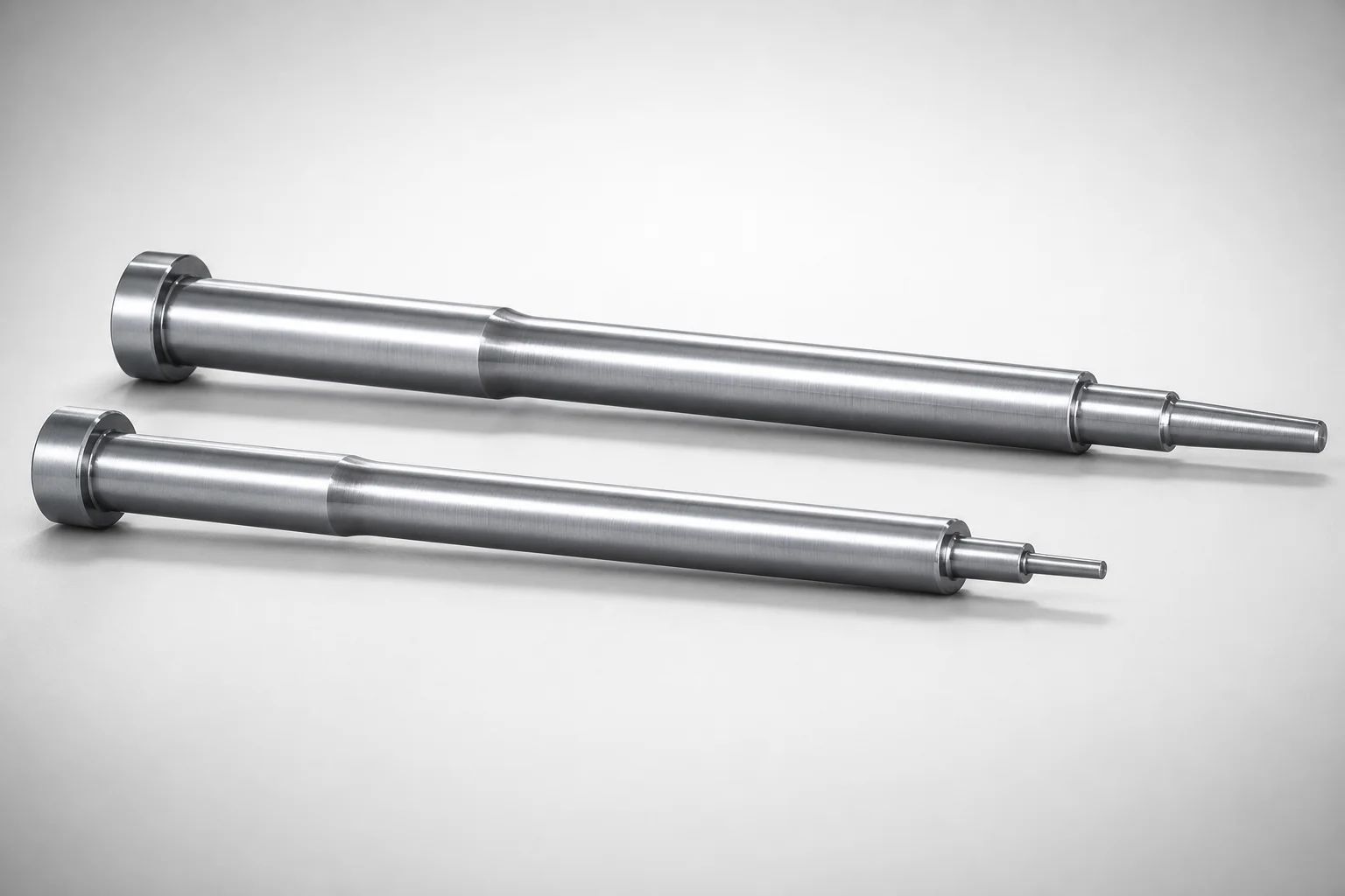
JIS Standard SKH51 Steel Stepped Two-Step Center Pins
Stepped two-step center pins (SKH51 steel) provide precise location and improved guiding stability in mold and die assembly. The stepped two-step geometry supports consistent centering during operation, even under repeated cycles.
- Stepped two-step form for controlled centering and stable alignment
- Quenched SKH51 steel with wear-resistant performance for long service life
- Tight shaft diameter tolerance (0 / -0.005 mm) to support accurate fit
- Typical use in tooling locating/centering where stable pin engagement is required
Specifications
400 configurations available
| D/P (Shaft Diameter) (mm) | Step Shape | D (Stepped root part diameter) (mm) | Type of the second step | A (Tip part) (mm) | C (Tip part) (mm) | E (Tip diameter in the tip part) (mm) | F (Shaft diameter length) (mm) | G (Tip C chamfering width on the tip part) (mm) | J (Tip part) (mm) | L (L dimension) (mm) | Dimension N (mm) | Q (Tip R chamfering on the tip part) (mm) | R (Tip part) (mm) | V (Tip diameter in the tip part) (mm) | Dimension Y (mm) | type |
|---|---|---|---|---|---|---|---|---|---|---|---|---|---|---|---|---|
| 1 ~ 1.49 | A | 1.5 | A | - | - | 0.5 ~ 1.47 | 55 ~ 199 | - | - | 70 ~ 200 | 25 ~ 169 | - | - | 0.5 ~ 1.48 | 55.5 ~ 199.5 | - |
| 1.5 ~ 1.99 | A | 2 | A | - | - | 0.7 ~ 1.98 | 5.5 ~ 249.5 | - | - | 70 ~ 250 | 25 ~ 220 | - | - | 0.7 ~ 1.98 | 55.5 ~ 249 | - |
| 1.5 ~ 2.49 | A | 2.5 | A | - | - | 0.7 ~ 2.48 | 55 ~ 249.5 | - | - | 70 ~ 250 | 25 ~ 220 | - | - | 0.7 ~ 2.48 | 55.5 ~ 249 | - |
| 2 ~ 2.99 | A | 3 | A | - | - | 1 ~ 2.98 | 5.5 ~ 299.5 | - | - | 100 ~ 300 | 25 ~ 270 | - | - | 1 ~ 2.98 | 55.5 ~ 299 | - |
| 2.5 ~ 3.49 | A | 3.5 | A | - | - | 1 ~ 3.48 | 5.5 ~ 299.9 | - | - | 100 ~ 300 | 25 ~ 270 | - | - | 1 ~ 3.48 | 55.5 ~ 299 | - |
| 3 ~ 3.99 | A | 4 | A | - | - | 1 ~ 3.98 | 5.5 ~ 299.5 | - | - | 100 ~ 300 | 25 ~ 270 | - | - | 1 ~ 3.98 | 55.5 ~ 299 | - |
| 3.5 ~ 4.49 | A | 4.5 | A | - | - | 1.5 ~ 4.48 | 5.5 ~ 299.9 | - | - | 100 ~ 300 | 25 ~ 270 | - | - | 1.5 ~ 4.48 | 55.5 ~ 299 | - |
| 4 ~ 4.99 | A | 5 | A | - | - | 1.5 ~ 4.98 | 55 ~ 349.5 | - | - | 100 ~ 350 | 25 ~ 320 | - | - | 1.5 ~ 4.98 | 55.5 ~ 349 | - |
| 5 ~ 5.49 | A | 5.5 | A | - | - | 1.5 ~ 5.48 | 55 ~ 349.5 | - | - | 100 ~ 350 | 25 ~ 320 | - | - | 1.5 ~ 5.48 | 55.5 ~ 349 | - |
| 5.5 ~ 5.99 | A | 6 | A | - | - | 2 ~ 5.98 | 55 ~ 349.5 | - | - | 100 ~ 350 | 25 ~ 320 | - | - | 2 ~ 5.98 | 55.5 ~ 349 | - |
| 6 ~ 6.49 | A | 6.5 | A | - | - | 2 ~ 6.48 | 55 ~ 349.5 | - | - | 100 ~ 350 | 25 ~ 320 | - | - | 2 ~ 6.48 | 55.5 ~ 349 | - |
| 6.5 ~ 6.99 | A | 7 | A | - | - | 2 ~ 6.98 | 55 ~ 349.5 | - | - | 100 ~ 350 | 25 ~ 320 | - | - | 2 ~ 6.98 | 55.5 ~ 349 | - |
| 7 ~ 7.99 | A | 8 | A | - | - | 2 ~ 7.98 | 55 ~ 349.5 | - | - | 100 ~ 350 | 25 ~ 320 | - | - | 2 ~ 7.98 | 55.5 ~ 349 | - |
| 8 ~ 8.99 | A | 9 | A | - | - | 2 ~ 8.98 | 55 ~ 349.5 | - | - | 100 ~ 350 | 25 ~ 320 | - | - | 2 ~ 8.98 | 55.5 ~ 349 | - |
| 9 ~ 9.99 | A | 10 | A | - | - | 2 ~ 9.98 | 55 ~ 349.5 | - | - | 100 ~ 350 | 25 ~ 320 | - | - | 2 ~ 9.98 | 55.5 ~ 349 | - |
| 10 ~ 11.99 | A | 12 | A | - | - | 2.5 ~ 11.98 | 55 ~ 349.5 | - | - | 100 ~ 350 | 25 ~ 320 | - | - | 2.5 ~ 11.98 | 55.5 ~ 349 | - |
| 1 ~ 1.49 | A | 1.5 | B | - | - | 0.5 ~ 1.47 | 55 ~ 198.6 | - | 0.5 ~ 1.47 | 70 ~ 200 | 25 ~ 168.6 | - | - | 0.51 ~ 1.48 | 55.7 ~ 199.7 | - |
| 1.5 ~ 1.99 | A | 2 | B | - | - | 0.7 ~ 1.98 | 55 ~ 249.5 | - | 0.7 ~ 1.98 | 70 ~ 250 | 25 ~ 220 | - | - | 0.7 ~ 1.98 | 55.5 ~ 249 | - |
| 1.5 ~ 2.49 | A | 2.5 | B | - | - | 0.7 ~ 2.48 | 55 ~ 249.5 | - | 0.7 ~ 2.48 | 70 ~ 250 | 25 ~ 220 | - | - | 0.7 ~ 2.48 | 55.5 ~ 249 | - |
| 2 ~ 2.99 | A | 3 | B | - | - | 1 ~ 2.98 | 55 ~ 299.5 | - | 1 ~ 2.98 | 100 ~ 300 | 25 ~ 270 | - | - | 1 ~ 2.98 | 55.5 ~ 299 | - |
| 2.5 ~ 3.49 | A | 3.5 | B | - | - | 1 ~ 3.48 | 55 ~ 299.9 | - | 1 ~ 3.48 | 100 ~ 300 | 25 ~ 270 | - | - | 1 ~ 3.48 | 55.5 ~ 299 | - |
| 3 ~ 3.99 | A | 4 | B | - | - | 1 ~ 3.98 | 55 ~ 299.5 | - | 1 ~ 3.98 | 100 ~ 300 | 25 ~ 270 | - | - | 1 ~ 3.98 | 55.5 ~ 299 | - |
| 3.5 ~ 4.49 | A | 4.5 | B | - | - | 1.5 ~ 4.48 | 55 ~ 299.9 | - | 1.5 ~ 4.48 | 100 ~ 300 | 25 ~ 270 | - | - | 1.5 ~ 4.48 | 55.5 ~ 299 | - |
| 4 ~ 4.99 | A | 5 | B | - | - | 1.5 ~ 4.98 | 55 ~ 349.5 | - | 1.5 ~ 4.98 | 100 ~ 350 | 25 ~ 320 | - | - | 1.5 ~ 4.98 | 55.5 ~ 349 | - |
| 5 ~ 5.49 | A | 5.5 | B | - | - | 1.5 ~ 5.48 | 55 ~ 349.5 | - | 1.5 ~ 5.48 | 100 ~ 350 | 25 ~ 320 | - | - | 1.5 ~ 5.48 | 55.5 ~ 349 | - |
| 5.5 ~ 5.99 | A | 6 | B | - | - | 2 ~ 5.98 | 55 ~ 349.5 | - | 2 ~ 5.98 | 100 ~ 350 | 25 ~ 320 | - | - | 2 ~ 5.98 | 55.5 ~ 349 | - |
| 6 ~ 6.49 | A | 6.5 | B | - | - | 2 ~ 6.48 | 55 ~ 349.5 | - | 2 ~ 6.48 | 100 ~ 350 | 25 ~ 320 | - | - | 2 ~ 6.48 | 55.5 ~ 349 | - |
| 6.5 ~ 6.99 | A | 7 | B | - | - | 2 ~ 6.98 | 55 ~ 349.5 | - | 2 ~ 6.98 | 100 ~ 350 | 25 ~ 320 | - | - | 2 ~ 6.98 | 55.5 ~ 349 | - |
| 7 ~ 7.99 | A | 8 | B | - | - | 2 ~ 7.98 | 55 ~ 349.5 | - | 2 ~ 7.98 | 100 ~ 350 | 25 ~ 320 | - | - | 2 ~ 7.98 | 55.5 ~ 349 | - |
| 8 ~ 8.99 | A | 9 | B | - | - | 2 ~ 8.98 | 55 ~ 349.5 | - | 2 ~ 8.98 | 100 ~ 350 | 25 ~ 320 | - | - | 2 ~ 8.98 | 55.5 ~ 349 | - |
| 9 ~ 9.99 | A | 10 | B | - | - | 2 ~ 9.98 | 55 ~ 349.5 | - | 2 ~ 9.98 | 100 ~ 350 | 25 ~ 320 | - | - | 2 ~ 9.98 | 55.5 ~ 349 | - |
| 10 ~ 11.99 | A | 12 | B | - | - | 2.5 ~ 11.98 | 55 ~ 349.5 | - | 2.5 ~ 11.98 | 100 ~ 350 | 25 ~ 320 | - | - | 2.5 ~ 11.98 | 55.5 ~ 349 | - |
| 1 ~ 1.49 | A | 1.5 | C | - | - | 0.5 ~ 1.47 | 55 ~ 199 | - | 0.5 ~ 1.47 | 70 ~ 200 | 25 ~ 169 | - | - | 0.51 ~ 1.48 | 55.5 ~ 199.5 | - |
| 1.5 ~ 1.99 | A | 2 | C | - | - | 0.7 ~ 1.98 | 55 ~ 249.5 | - | 0.7 ~ 1.98 | 70 ~ 250 | 25 ~ 220 | - | - | 0.7 ~ 1.98 | 55.5 ~ 249 | - |
| 1.5 ~ 2.49 | A | 2.5 | C | - | - | 0.7 ~ 2.48 | 55 ~ 249.5 | - | 0.7 ~ 2.48 | 70 ~ 250 | 25 ~ 220 | - | - | 0.7 ~ 2.48 | 55.5 ~ 249 | - |
| 2 ~ 2.99 | A | 3 | C | - | - | 1 ~ 2.98 | 55 ~ 299.5 | - | 1 ~ 2.98 | 100 ~ 300 | 25 ~ 270 | - | - | 1 ~ 2.98 | 55.5 ~ 299 | - |
| 2.5 ~ 3.49 | A | 3.5 | C | - | - | 1 ~ 3.48 | 55 ~ 299.9 | - | 1 ~ 3.48 | 100 ~ 300 | 25 ~ 270 | - | - | 1 ~ 3.48 | 55.5 ~ 299 | - |
| 3 ~ 3.99 | A | 4 | C | - | - | 1 ~ 3.98 | 55 ~ 299.5 | - | 1 ~ 3.98 | 100 ~ 300 | 25 ~ 270 | - | - | 1 ~ 3.98 | 55.5 ~ 299 | - |
| 3.5 ~ 4.49 | A | 4.5 | C | - | - | 1.5 ~ 4.48 | 55 ~ 299.5 | - | 1.5 ~ 4.48 | 100 ~ 300 | 25 ~ 270 | - | - | 1.5 ~ 4.48 | 55.5 ~ 299 | - |
| 4 ~ 4.99 | A | 5 | C | - | - | 1.5 ~ 4.98 | 55 ~ 349.5 | - | 1.5 ~ 4.98 | 100 ~ 350 | 25 ~ 320 | - | - | 1.5 ~ 4.98 | 55.5 ~ 349 | - |
| 5 ~ 5.49 | A | 5.5 | C | - | - | 1.5 ~ 5.48 | 55 ~ 349.5 | - | 1.5 ~ 5.48 | 100 ~ 350 | 25 ~ 320 | - | - | 1.5 ~ 5.48 | 55.5 ~ 349 | - |
| 5.5 ~ 5.99 | A | 6 | C | - | - | 2 ~ 5.98 | 55 ~ 349.5 | - | 2 ~ 5.98 | 100 ~ 350 | 25 ~ 320 | - | - | 2 ~ 5.98 | 55.5 ~ 349 | - |
| 6 ~ 6.49 | A | 6.5 | C | - | - | 2 ~ 6.48 | 55 ~ 349.5 | - | 2 ~ 6.48 | 100 ~ 350 | 25 ~ 320 | - | - | 2 ~ 6.48 | 55.5 ~ 349 | - |
| 6.5 ~ 6.99 | A | 7 | C | - | - | 2 ~ 6.98 | 55 ~ 349.5 | - | 2 ~ 6.98 | 100 ~ 350 | 25 ~ 320 | - | - | 2 ~ 6.98 | 55.5 ~ 349 | - |
| 7 ~ 7.99 | A | 8 | C | - | - | 2 ~ 7.98 | 55 ~ 349.5 | - | 2 ~ 7.98 | 100 ~ 350 | 25 ~ 320 | - | - | 2 ~ 7.98 | 55.5 ~ 349 | - |
| 8 ~ 8.99 | A | 9 | C | - | - | 2 ~ 8.98 | 55 ~ 349.5 | - | 2 ~ 8.98 | 100 ~ 350 | 25 ~ 320 | - | - | 2 ~ 8.98 | 55.5 ~ 349 | - |
| 9 ~ 9.99 | A | 10 | C | - | - | 2 ~ 9.98 | 55 ~ 349.5 | - | 2 ~ 9.98 | 100 ~ 350 | 25 ~ 320 | - | - | 2 ~ 9.98 | 55.5 ~ 349 | - |
| 10 ~ 11.99 | A | 12 | C | - | - | 2.5 ~ 11.98 | 55 ~ 349.5 | - | 2.5 ~ 11.98 | 100 ~ 350 | 25 ~ 320 | - | - | 2.5 ~ 11.98 | 55.5 ~ 349 | - |
| 1 ~ 1.49 | A | 1.5 | D | - | - | 0.5 ~ 1.47 | 55 ~ 199 | 0.1 ~ 0.5 | 0.5 ~ 1.47 | 70 ~ 200 | 25 ~ 169 | - | - | 0.51 ~ 1.48 | 55.5 ~ 199.5 | - |
| 1.5 ~ 1.99 | A | 2 | D | - | - | 0.7 ~ 1.98 | 55 ~ 249.5 | 0.1 ~ 0.5 | 0.7 ~ 1.98 | 70 ~ 250 | 25 ~ 220 | - | - | 0.7 ~ 1.98 | 55.5 ~ 249 | - |
Product Guide
Application Scenarios+
Stepped two-step center pins are used in injection mold tooling and die assemblies where repeatable part positioning and guiding stability are critical. The stepped geometry creates controlled engagement at two levels, helping maintain centering and reducing lateral drift during high-cycle operation.
- Automotive connector and small housing molds: Ideal for locating features that must align under repeated clamping, because the two-step engagement improves stable alignment as the pin repeatedly mates with bushings/locating holes.
- Medical device housings and precision enclosures: Suited for guiding thin, precision inserts where consistent concentricity matters; the variant’s stepped two-step form supports reliable centering during cycle-to-cycle variation.
- General die sets with tight locating fits: Works well when the assembly requires accurate shaft-to-hole relationship; the tight shaft tolerance supports dependable guidance and stable pin engagement.
This variant is matched to precision locating/centering roles, combining a wear-resistant steel selection with tight shaft dimensional control.
Material & Process Details+
This product is made from JIS Standard SKH51 steel, commonly used for wear-resistant, precision tooling components. While SKH51 is a high-performance tool steel, its key advantage here is its quenched condition for improved hardness and resistance to wear at the pin-to-locating interface.
- Heat treatment state: Quenched SKH51 steel (as specified for this variant).
- Property focus: Enhanced wear resistance for long service life under repeated sliding/engagement.
- Trade-off: As hardness increases, extreme toughness and impact resistance may be comparatively lower than tougher grades—making it important to avoid applications with severe shock loading.
If your application demands higher toughness over wear, alternative steel grades may be considered; however, this SKH51 variant targets stable guiding and controlled centering with wear durability.
Sizing & Selection Guide+
Select the center pin dimensions by matching the locating requirements of the mold core/cavity interface and the mating holes/bushings. Start with the D/P (shaft diameter) in the range 1 to 10 mm, and confirm the intended fit using the available shaft tolerance: 0 / -0.005 mm.
- Choose the stepped geometry: Select the Step Shape (A, B, C, D, E) and the corresponding second step type (A, B, C, D, E) to align with your two-level locating pattern.
- Verify stepped root and tip sizes: Set D (stepped root diameter) within 1.5 to 12 mm, and select tip dimensions such as A (0.51 to 2.5 mm) and E (0.5 to 2.5 mm). Tip chamfer widths (G) are fixed in the 0.1 to 0.5 mm range per model data.
- Match length: Use the specified F (shaft diameter length) of 5.5 to 55 mm and overall L ranges (e.g., 70–200, 70–250, 100–300, 100–350, 100–250) to ensure correct engagement depth.
Account for the pin’s tight shaft tolerance when selecting the mating bore size; the pin is dimensioned to a controlled maximum with limited negative deviation to support repeatable guidance.
Frequently Asked Questions
Which shaft diameter range (D/P) is available for SKH51 stepped two-step center pins, and how tight is the fit tolerance?+
The D/P (shaft diameter) range is 1 to 10 mm. The product data specifies a tight shaft tolerance of 0 / -0.005 mm, which helps maintain accurate guidance fit in the locating interface.
How do I select the correct two-step profile when the mold requires engagement at two levels?+
Use the Step Shape options (A, B, C, D, E) and match the second step type (A, B, C, D, E) to your mold’s two-level locating pattern. Then verify that the stepped root diameter D stays within 1.5 to 12 mm and that the tip dimensions (e.g., A and E) match the mating features.
What heat treatment condition is specified for the SKH51 center pin variant, and what performance does it target?+
The variant is described as quenched SKH51 steel. This heat-treated state is intended to improve wear-resistant performance for long service life under repeated pin engagement and guiding cycles.
How should I choose the pin length (F and L) to ensure correct engagement without over-insertion?+
Match F (shaft diameter length) within 5.5 to 55 mm to the required straight guiding engagement depth. Then select L based on the available ranges in the spec set (e.g., 70–200, 70–250, 100–300, 100–350, 100–250) so the pin properly engages the locating feature without excessive reach.
Are tip geometry parameters configurable, and which values are fixed versus variable?+
Several tip geometry parameters are configurable through the selected model dimensions, including A (tip part) from 0.51 to 2.5 mm, E (tip diameter in the tip part) from 0.5 to 2.5 mm, and J (tip part) from 0.5 to 2.5 mm. The tip C chamfering width C is fixed as 0.1 to 1.5 mm in the given data, and G is fixed as 0.1 to 0.5 mm for chamfer width.
Related Products
Need Custom Specifications?
Our engineering team can help with custom configurations, material selection, and volume pricing.