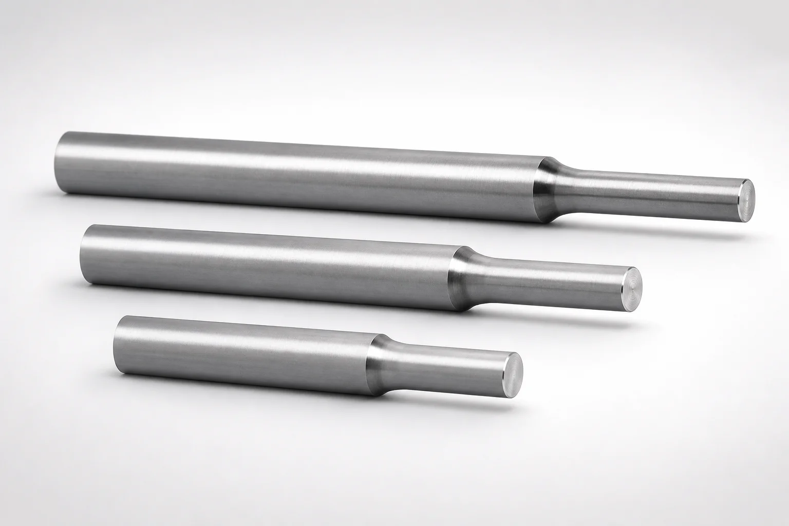
JIS Standard SKH51 Steel Stepped Ejector Pins with Engraving
Stepped ejector pins with engraving (SKH51 steel) are built for precise mold ejection and repeatable positioning in tooling assemblies. The stepped geometry and engraved identification support clean setup and controlled cycle performance.
- Stepped profile improves guidance and supports consistent ejection alignment
- SKH51 steel construction with hardening for reliable wear resistance during production
- Shaft diameter tolerance reference 0/-0.02 helps maintain stable fits in the guide system
- JIS-standard pin design suited for die and mold fabrication using engraved part designation
Specifications
1024 configurations available
| Tip Diameter Tolerance Reference | Head Thickness | D (Shaft Diameter) (mm) | P (Tip Diameter) (mm) | Character Engraving Type | Number of Outer Ring Characters | L (L dimension) (mm) | Dimension N (mm) | # | Character Engraving (Number designation) | Engraving character designation | Engraving character selection | type |
|---|---|---|---|---|---|---|---|---|---|---|---|---|
| 0/-0.005 | 4mm(T4) | 1 | 0.3 ~ 0.9 | Concave character | 1 characters | 40 ~ 150 | 15 ~ 135 | - | - | - | & | - |
| 0/-0.005 | 4mm(T4) | 1 | 0.3 ~ 0.9 | Concave character | 1 characters | 40 ~ 150 | 15 ~ 135 | # | - | - | - | - |
| 0/-0.005 | 4mm(T4) | 1 | 0.3 ~ 0.9 | Concave character | 1 characters | 40 ~ 150 | 15 ~ 135 | - | - | - | % (Space) | - |
| 0/-0.005 | 4mm(T4) | 1 | 0.3 ~ 0.9 | Concave character | 1 characters | 40 ~ 150 | 15 ~ 135 | - | - | - | + | - |
| 0/-0.005 | 4mm(T4) | 1 | 0.3 ~ 0.9 | Concave character | 1 characters | 40 ~ 150 | 15 ~ 135 | - | - | - | < | - |
| 0/-0.005 | 4mm(T4) | 1 | 0.3 ~ 0.9 | Concave character | 1 characters | 40 ~ 150 | 15 ~ 135 | - | - | - | > | - |
| 0/-0.005 | 4mm(T4) | 1 | 0.3 ~ 0.9 | Concave character | 1 characters | 40 ~ 150 | 15 ~ 135 | - | - | - | @ | - |
| 0/-0.005 | 4mm(T4) | 1 | 0.3 ~ 0.9 | Concave character | 1 characters | 40 ~ 150 | 15 ~ 135 | - | - | - | A | - |
| 0/-0.005 | 4mm(T4) | 1 | 0.3 ~ 0.9 | Concave character | 1 characters | 40 ~ 150 | 15 ~ 135 | - | 0 ~ 9 | - | - | - |
| 0/-0.005 | 4mm(T4) | 1 | 0.3 ~ 0.9 | Concave character | 1 characters | 40 ~ 150 | 15 ~ 135 | - | - | - | B | - |
| 0/-0.005 | 4mm(T4) | 1 | 0.3 ~ 0.9 | Concave character | 1 characters | 40 ~ 150 | 15 ~ 135 | - | - | - | C | - |
| 0/-0.005 | 4mm(T4) | 1 | 0.3 ~ 0.9 | Concave character | 1 characters | 40 ~ 150 | 15 ~ 135 | - | - | - | D | - |
| 0/-0.005 | 4mm(T4) | 1 | 0.3 ~ 0.9 | Concave character | 1 characters | 40 ~ 150 | 15 ~ 135 | - | - | - | E | - |
| 0/-0.005 | 4mm(T4) | 1 | 0.3 ~ 0.9 | Concave character | 1 characters | 40 ~ 150 | 15 ~ 135 | - | - | - | F | - |
| 0/-0.005 | 4mm(T4) | 1 | 0.3 ~ 0.9 | Concave character | 1 characters | 40 ~ 150 | 15 ~ 135 | - | - | - | G | - |
| 0/-0.005 | 4mm(T4) | 1 | 0.3 ~ 0.9 | Concave character | 1 characters | 40 ~ 150 | 15 ~ 135 | - | - | - | H | - |
| 0/-0.005 | 4mm(T4) | 1 | 0.3 ~ 0.9 | Concave character | 1 characters | 40 ~ 150 | 15 ~ 135 | - | - | - | I | - |
| 0/-0.005 | 4mm(T4) | 1 | 0.3 ~ 0.9 | Concave character | 1 characters | 40 ~ 150 | 15 ~ 135 | - | - | - | J | - |
| 0/-0.005 | 4mm(T4) | 1 | 0.3 ~ 0.9 | Concave character | 1 characters | 40 ~ 150 | 15 ~ 135 | - | - | - | K | - |
| 0/-0.005 | 4mm(T4) | 1 | 0.3 ~ 0.9 | Concave character | 1 characters | 40 ~ 150 | 15 ~ 135 | - | - | - | L | - |
| 0/-0.005 | 4mm(T4) | 1 | 0.3 ~ 0.9 | Concave character | 1 characters | 40 ~ 150 | 15 ~ 135 | - | - | - | M | - |
| 0/-0.005 | 4mm(T4) | 1 | 0.3 ~ 0.9 | Concave character | 1 characters | 40 ~ 150 | 15 ~ 135 | - | - | - | N | - |
| 0/-0.005 | 4mm(T4) | 1 | 0.3 ~ 0.9 | Concave character | 1 characters | 40 ~ 150 | 15 ~ 135 | - | - | - | O | - |
| 0/-0.005 | 4mm(T4) | 1 | 0.3 ~ 0.9 | Concave character | 1 characters | 40 ~ 150 | 15 ~ 135 | - | - | - | P | - |
| 0/-0.005 | 4mm(T4) | 1 | 0.3 ~ 0.9 | Concave character | 1 characters | 40 ~ 150 | 15 ~ 135 | - | - | - | Q | - |
| 0/-0.005 | 4mm(T4) | 1 | 0.3 ~ 0.9 | Concave character | 1 characters | 40 ~ 150 | 15 ~ 135 | - | - | - | R | - |
| 0/-0.005 | 4mm(T4) | 1 | 0.3 ~ 0.9 | Concave character | 1 characters | 40 ~ 150 | 15 ~ 135 | - | - | - | S | - |
| 0/-0.005 | 4mm(T4) | 1 | 0.3 ~ 0.9 | Concave character | 1 characters | 40 ~ 150 | 15 ~ 135 | - | - | - | T | - |
| 0/-0.005 | 4mm(T4) | 1 | 0.3 ~ 0.9 | Concave character | 1 characters | 40 ~ 150 | 15 ~ 135 | - | - | - | U | - |
| 0/-0.005 | 4mm(T4) | 1 | 0.3 ~ 0.9 | Concave character | 1 characters | 40 ~ 150 | 15 ~ 135 | - | - | - | V | - |
| 0/-0.005 | 4mm(T4) | 1 | 0.3 ~ 0.9 | Concave character | 1 characters | 40 ~ 150 | 15 ~ 135 | - | - | - | W | - |
| 0/-0.005 | 4mm(T4) | 1 | 0.3 ~ 0.9 | Concave character | 1 characters | 40 ~ 150 | 15 ~ 135 | - | - | - | X | - |
| 0/-0.005 | 4mm(T4) | 1 | 0.3 ~ 0.9 | Concave character | 1 characters | 40 ~ 150 | 15 ~ 135 | - | - | - | Y | - |
| 0/-0.005 | 4mm(T4) | 1 | 0.3 ~ 0.9 | Concave character | 1 characters | 40 ~ 150 | 15 ~ 135 | - | - | - | Z | - |
| 0/-0.005 | 4mm(T4) | 1 | 0.3 ~ 0.9 | Concave character | 1 characters | 40 ~ 150 | 15 ~ 135 | - | - | - | \(/) | - |
| 0/-0.005 | 4mm(T4) | 1 | 0.3 ~ 0.9 | Concave character | 1 characters | 40 ~ 150 | 15 ~ 135 | - | - | ※Designation by WOS | - | - |
| 0/-0.005 | 4mm(T4) | 1.5 | 0.6 ~ 1.4 | Concave character | 1 characters | 40 ~ 200 | 15 ~ 185 | - | - | - | + | - |
| 0/-0.005 | 4mm(T4) | 1.5 | 0.6 ~ 1.4 | Concave character | 1 characters | 40 ~ 200 | 15 ~ 185 | - | - | - | & | - |
| 0/-0.005 | 4mm(T4) | 1.5 | 0.6 ~ 1.4 | Concave character | 1 characters | 40 ~ 200 | 15 ~ 185 | # | - | - | - | - |
| 0/-0.005 | 4mm(T4) | 1.5 | 0.6 ~ 1.4 | Concave character | 1 characters | 40 ~ 200 | 15 ~ 185 | - | - | - | % (Space) | - |
| 0/-0.005 | 4mm(T4) | 1.5 | 0.6 ~ 1.4 | Concave character | 1 characters | 40 ~ 200 | 15 ~ 185 | - | - | - | < | - |
| 0/-0.005 | 4mm(T4) | 1.5 | 0.6 ~ 1.4 | Concave character | 1 characters | 40 ~ 200 | 15 ~ 185 | - | - | - | > | - |
| 0/-0.005 | 4mm(T4) | 1.5 | 0.6 ~ 1.4 | Concave character | 1 characters | 40 ~ 200 | 15 ~ 185 | - | - | - | @ | - |
| 0/-0.005 | 4mm(T4) | 1.5 | 0.6 ~ 1.4 | Concave character | 1 characters | 40 ~ 200 | 15 ~ 185 | - | - | - | A | - |
| 0/-0.005 | 4mm(T4) | 1.5 | 0.6 ~ 1.4 | Concave character | 1 characters | 40 ~ 200 | 15 ~ 185 | - | 0 ~ 9 | - | - | - |
| 0/-0.005 | 4mm(T4) | 1.5 | 0.6 ~ 1.4 | Concave character | 1 characters | 40 ~ 200 | 15 ~ 185 | - | - | - | B | - |
| 0/-0.005 | 4mm(T4) | 1.5 | 0.6 ~ 1.4 | Concave character | 1 characters | 40 ~ 200 | 15 ~ 185 | - | - | - | C | - |
| 0/-0.005 | 4mm(T4) | 1.5 | 0.6 ~ 1.4 | Concave character | 1 characters | 40 ~ 200 | 15 ~ 185 | - | - | - | D | - |
| 0/-0.005 | 4mm(T4) | 1.5 | 0.6 ~ 1.4 | Concave character | 1 characters | 40 ~ 200 | 15 ~ 185 | - | - | - | E | - |
| 0/-0.005 | 4mm(T4) | 1.5 | 0.6 ~ 1.4 | Concave character | 1 characters | 40 ~ 200 | 15 ~ 185 | - | - | - | F | - |
Product Guide
Application Scenarios+
These stepped ejector pins with engraved identification are used in injection mold build-ups where stable ejection guidance and repeatable assembly alignment are critical. The stepped geometry helps provide controlled lateral support as the pin retracts and advances, reducing misalignment-related wear in the guide system.
- Automotive and electronics connector molds: Suitable for multi-cavity tooling that benefits from consistent positioning between insert assemblies; the step profile supports predictable ejection travel and helps maintain stable fits.
- General die/mold fabrication with part traceability: The engraved character/number designation (concave character, including sequential numbering) streamlines maintenance and rebuilds by making pin identification visible on the tooling.
- High-cycle housings and small components: SKH51 steel is engineered for durable service, supporting reliable ejection stability in production environments where wear resistance is required.
Choose this variant when you need both guided ejection performance and clear engraving for build-up and inspection workflows.
Material & Process Details+
SKH51 is a JIS standard tool steel used for cutting and wear-critical applications; in mold engineering practice it is commonly selected as an AISI M2–equivalent high-speed steel grade for good hot-wear resistance and dimensional stability under repeated cycles.
- Heat treatment state: Typically supplied as hardened tool steel suitable for quenched and tempered service; final hardness should be confirmed against the manufacturer’s receiving specs for the intended pin size and application load.
- Hardness & trade-offs: Expect a hardened condition with high hardness (often in the HRC range for HSS tooling) that improves wear resistance, while toughness may be lower than lower-alloy steels if driven to extremes in impact conditions.
- Wear vs. toughness: Compared with general die steels, SKH51 prioritizes wear resistance for ejector guidance surfaces; compared with lower-hardness grades, it may be less forgiving under shock loads.
Where toughness is the primary concern, select an alternative grade; where abrasion and repeated ejection cycles dominate, SKH51 is a strong fit.
Sizing & Selection Guide+
Select ejector pin dimensions by matching the shaft diameter D (1 ~ 12 mm) and tip diameter P (0.3 ~ 8.9 mm) to the corresponding ejector plate and guide bore geometry. For guided molds, the shaft-to-guide fit is especially important; this series provides a tip diameter tolerance reference of 0/-0.005 or -0.01/-0.02, so confirm which tolerance class is required for your guide clearance.
- Length L (40 ~ 150, 40 ~ 200, 40 ~ 250, 40 ~ 250, 50 ~ 250 mm options): Choose based on the stroke clearance and required engagement length through the mold stack-up.
- Dimension N (15 ~ 135, 15 ~ 185, 15 ~ 235, 15 ~ 230, 15 ~ 220, 30 ~ 230 mm options): Use N to match how far the stepped portion and seating feature extend within the assembly.
- Head thickness: Select T4 (4 mm) or 6 mm / 8 mm (JIS) to ensure proper seating and retention.
All engraving options are configurable, but the mechanical dimensions (D, P, L, N) must be selected to match your core/cavity and guide interfaces within the provided tolerance references.
Frequently Asked Questions
What tip diameter tolerance reference is available for these SKH51 stepped ejector pins?+
The product provides tip diameter tolerance references of 0/-0.005 and -0.01/-0.02 (depending on the selected size/variant). Use the tighter negative tolerance when your guide bore clearance must be controlled for stable ejection alignment.
How do I choose the correct shaft diameter D for the guide system?+
Shaft diameter D is specified in the range 1 ~ 12 mm. Match D to your ejector guide bore so the shaft can slide with the intended clearance; then select the appropriate tip tolerance reference to keep the stepped alignment stable during cycle operation.
Which length options should I use for L and N in a multi-plate mold build-up?+
Choose L from the available ranges: 40 ~ 150, 40 ~ 200, 40 ~ 250, 40 ~ 250 (listed), or 50 ~ 250 mm. Then select N from the provided options (e.g., 15 ~ 135, 15 ~ 185, 15 ~ 235, 15 ~ 230, 15 ~ 220, or 30 ~ 230 mm) to align the stepped portion seating within your mold stack-up.
What head thickness options are available and how do they affect assembly seating?+
Head thickness is available as 4 mm (T4) or 6 mm / 8 mm (JIS). Select the thickness that matches your ejector plate interface so the pin seats correctly and maintains consistent retention during ejection cycles.
What engraving formats are supported for traceability on these ejector pins?+
Engraving uses concave characters, including sequential numbering variants. You can configure the number of outer ring characters (from 1 to 5) and select design characters including digits (0 ~ 9, 1 ~ 9) and symbols such as &, %, +, <, >, @ plus additional selectable characters.
Related Products
Need Custom Specifications?
Our engineering team can help with custom configurations, material selection, and volume pricing.